Maker Pro
Maker Pro

PIR operated DC motor project odd behaviour help

spyder9

Feb 15, 2017
61
Joined
Feb 15, 2017
Messages
61
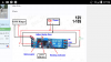
When I connect like this picture i get 12v across opto input,when i connect red and black it triggers signal and after a set period of time it turns off,like it should
But when i connect vibration motor wires signal Is always on,no matter Is it ringing or not.
Haven't tried another way to connect,one that You have sent me recently.

Ivan
 

Attachments

  • received_1427194740683645.png
    received_1427194740683645.png
    191.7 KB · Views: 106

CDRIVE

Hauling 10' pipe on a Trek Shift3
May 8, 2012
4,960
Joined
May 8, 2012
Messages
4,960
Unfortunately I'm not psychic and I'm running out of ideas. Perhaps it's time or possibly long past due that you post sharp photos of your setup. Maybe we'll see a clue in the pix .

Chris
 

spyder9

Feb 15, 2017
61
Joined
Feb 15, 2017
Messages
61
I can't upload a video,it is too large,even with rendering i got it to 5mb,still can't upload

When i turn on supply,opto input wires (red and black) when measured with DMM shows 10.45V. and only Power LED is working

When I touch them together motor starts,both LED's are working,and when i seperate them motor stops after 4-5 seconds,because i set it like that.

When i connect + and - wires from vibration motor,controled motor starts,both LED's are working but motor never stops and LED's never turn off,only when i disconnect vibration motor wires does the motor stops.

Ivan
 

CDRIVE

Hauling 10' pipe on a Trek Shift3
May 8, 2012
4,960
Joined
May 8, 2012
Messages
4,960
Just post stills or upload the video to youtube?

Chris
 

CDRIVE

Hauling 10' pipe on a Trek Shift3
May 8, 2012
4,960
Joined
May 8, 2012
Messages
4,960
Hello Ivan,
I'm involved in another topic that involves a timeout period. I then remembered your project utilized a timer module purchased on Ebay which brought me back to this topic. When I followed the Ebay link to your timer module I had an "OH SH!T!" moment because I knew I screwed up!

Ivan, if you're still working on this project please post soon. I know why you're module isn't working properly and it's not your fault. It's totally MY FAULT! :oops::(

This is the interface that I provided you. The Optocoupler interface is very wrong!:eek: Fortunately, the fix should only require an NPN Transistor and one Resistor.

When you reply I'll fully explain how (I think) my screw up happened. I have loads of pathetic excuses.

Chris

EDIT: I think I'm actually having a lucid moment. So while my brain is still in active mode I think I should edit this post lest I forget. Ivan, if you're handy with an exacto-knife we probably can eliminate the NPN I mentioned.
upload_2017-10-10_11-51-20.png
 
Last edited:

spyder9

Feb 15, 2017
61
Joined
Feb 15, 2017
Messages
61
Hello sir,i am here now
I was away for some time but now i'm determined to finish this projec
 

CDRIVE

Hauling 10' pipe on a Trek Shift3
May 8, 2012
4,960
Joined
May 8, 2012
Messages
4,960
Hello Ivan,
I'm reasonably sure that we went through this before but we're going to do it again.

(1) Disconnect the GSM from the timer module.
(2) Apply power to the timer module.
(3) Place your DMM on DC Volts scale.
(4) Measure voltage present across the opto input jack.
(5) Record voltage and polarity.
(6) Post results.

Chris
upload_2017-10-31_9-48-16.png
 

CDRIVE

Hauling 10' pipe on a Trek Shift3
May 8, 2012
4,960
Joined
May 8, 2012
Messages
4,960
OK, that explains the seemingly strange behavior when connected to your GSM ringer output.

The next test is to determine if the vibrator motor is Low or High side switched. Low Side switching is more common in electronics circuitry.

GSM (High / Low) Switching Test:
(1) Turn your GSM on.
(2) Set your DMM to DC Volts.
(3) Connect the Black (-) DMM probe to the negative battery or power supply terminal. This will be your GSM ground.
(4) Measure for voltage at either terminal of the vibrator motor while it's NOT ringing.

If you measure voltage while it's not ringing then the vibrator motor is switched from the Low Side and the next test will determine which vibrator terminal is switched to ground.

Measure each vibrator terminal while the GSM is ringing. The vibrator terminal that drops to near 0V will be the switched leg.

Post your results.

Chris
 

spyder9

Feb 15, 2017
61
Joined
Feb 15, 2017
Messages
61
When it Is only powered on but not ringing
When i connect (-) from DMM to it's battery and measure voltage on both + and - output i get 0v.
When it is ringing i get 0v on (-) and 3.30v to 0 intervals on (+)
 

CDRIVE

Hauling 10' pipe on a Trek Shift3
May 8, 2012
4,960
Joined
May 8, 2012
Messages
4,960
OK, that indicates that the GSM switches the vibrator motor from the (high side) positive rail. I don't think you want to do any exacto-knife surgery on your timer board. So I'm going to give you a one transistor interface. I'll post it within the next hour.

Chris
 

CDRIVE

Hauling 10' pipe on a Trek Shift3
May 8, 2012
4,960
Joined
May 8, 2012
Messages
4,960
This is an alternative to timer board surgery. I indicate a 2N2222 but just about any general purpose small signal NPN will do.

Chris

upload_2017-11-1_15-9-31.png
 

spyder9

Feb 15, 2017
61
Joined
Feb 15, 2017
Messages
61
Thank you sir.
I will try this tomorrow, i must go and get this NPN and resistor.
Just to make sure, i need to leave (-) wire from the vibration motor not connected to anything?
And only use (+) From the motor
And (-) from the battery
 

CDRIVE

Hauling 10' pipe on a Trek Shift3
May 8, 2012
4,960
Joined
May 8, 2012
Messages
4,960
Thank you sir.
I will try this tomorrow, i must go and get this NPN and resistor.
Just to make sure, i need to leave (-) wire from the vibration motor not connected to anything?
Actually this won't matter. Even if you left the motor connected this circuit will work in parallel with it. That said, since it isn't required for your application I would disconnect it.
And only use (+) From the motor
And (-) from the battery
 

CDRIVE

Hauling 10' pipe on a Trek Shift3
May 8, 2012
4,960
Joined
May 8, 2012
Messages
4,960
Hey, I forgot to mention.... If you're interests continue down the road of electronics you really need to learn the art of cannibalization and re-purposing. This can be imperative for the young (financially deprived) or those in areas that components are difficult to obtain. :)

Chris
 

spyder9

Feb 15, 2017
61
Joined
Feb 15, 2017
Messages
61
Connected as shown but I only get power LED on the timer module.
(-) From the GSM vibrator motor and (-) opto input Are not connected to anything.
 

CDRIVE

Hauling 10' pipe on a Trek Shift3
May 8, 2012
4,960
Joined
May 8, 2012
Messages
4,960
Connected as shown but I only get power LED on the timer module.
(-) From the GSM vibrator motor and (-) opto input Are not connected to anything.

That's not what I drew. GSM battery (-) should be connected to Opto jack (-) Black.

Chris
 

spyder9

Feb 15, 2017
61
Joined
Feb 15, 2017
Messages
61
Now both LED-s Are lit and motor Is turning but again it wont stop.

Edit:
Voltage between colector (which Is connected to opto input (+)) and emitter (opto (-)) Is 0.89v
 
Last edited:

CDRIVE

Hauling 10' pipe on a Trek Shift3
May 8, 2012
4,960
Joined
May 8, 2012
Messages
4,960
Now both LED-s Are lit and motor Is turning but again it wont stop.

Edit:
Voltage between colector (which Is connected to opto input (+)) and emitter (opto (-)) Is 0.89v
That's higher than I'd expect. I would think it would be closer to 0.30V because the LED in the Opto doesn't pull much current. That said that voltage is close enough to GND to turn the Opto LED on. So that's not the problem.

The voltage between the Collector and Emitter should inversely follow the vibrator voltage as it switches High and Low.

Here's another test:

(1) Divorce the GSM from the Timer board.
(2) Power up the Timer board.
(3) Monitor the Opto + - input with your DMM
(4) Momentarily short the Opto + - Input.
(5) Make note of voltage reading immediately after opening the short.

I would expect ~+12V when open and ~0V when shorted.

If all else fails post a clear photo.

Chris
 
Top