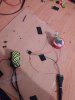
So i started making PIR sensor operated dc motor
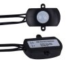
I got pir sensor switch with + and - input and output ports
When i connect dc to output ports it starts when it detects signal,but doesn't stop ever.
But when I plug multimeter on the output current stops when there is no signal
i can't figure out why
Maybe some resistors between pir out and dc ?
OK, I had to go back to your original post to verify this. You didn't specify this but should we assume that only the multimeter is connected to the output (no motor) when measuring? Did you try driving only a resistive load?
You never did answer my questions about your motor specs. Please post them and or a link to your motor. You may well be overtaxing the output capabilities of your detector. For all we know your also exceeding the capabilities of your power source. Is it a wallwart? Motors can pull many times their run current when starting.
Not knowing anything about your motor and taking into account (if I assume correctly) that it works as expected when only the multimeter is connected to the output, I think you'd be well advised to use the output voltage to drive a Relay or Transistor switch. There's a good chance that you may need a separate power supply for the motor as well. On the other hand this might be a decoupling issue that might be cured with some bypassing caps on the detector's output.
BTW, the flyback Diode that you added is something you should have done from the get go but I think you know that.
Chris
 Are you omitting important details, like your no longer using a 5V supply?