AlmightyJu
- Nov 17, 2012
- 7
- Joined
- Nov 17, 2012
- Messages
- 7
Hi, I'm new and the names julian and I'm all new to this electronic stuff (I'm a programmer) and decided to have a go at making a circuit to start my car with a button (which started with the loss of my car keys  !) and I'm just after some advice please
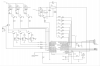
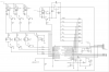
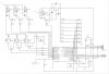
In short I just want to check if my calculations are right with the transistors/resistors so I don't blow anything up since its not going to be a fun situation if they do! - ignore the pic since I haven't worked all that out yet, although it seems pretty straight forward with just a few caps here and there
I've only got a couple of questions besides that to do with current, the pic can supply/sink 20mA per pin, is there a lowest amount of current needed for the pic to "see" it or is it just voltage driven? and also on my circuit i've got 7 buttons each with their own resistor and i did that because I'm not sure if having just one resistor before all the buttons would be ok if say 2 or 3 buttons were pushed at the same time.
Finally in the pdf linked below on page 55 is the wiring for my car, and I'm basically replacing the "IGNITION SW" with relays, but the fuse Amps confuse me because the main amp before the switch is less than all the smaller fuses after the switch, so I'm a little worried about what happens if something spikes and takes a relay out (hence the 30A and 40A relays). Is there any suggestions maybe on things I can read that might help?
My circuit is here and the pdf of my car wiring is here.
Sorry for the long post with lots of questions, I'm just a little unsure at this point about some things and thought I would ask from people who will know
Thanks
!) and I'm just after some advice please In short I just want to check if my calculations are right with the transistors/resistors so I don't blow anything up
since its not going to be a fun situation if they do! - ignore the pic since I haven't worked all that out yet, although it seems pretty straight forward with just a few caps here and there I've only got a couple of questions besides that to do with current, the pic can supply/sink 20mA per pin, is there a lowest amount of current needed for the pic to "see" it or is it just voltage driven? and also on my circuit i've got 7 buttons each with their own resistor and i did that because I'm not sure if having just one resistor before all the buttons would be ok if say 2 or 3 buttons were pushed at the same time.
Finally in the pdf linked below on page 55 is the wiring for my car, and I'm basically replacing the "IGNITION SW" with relays, but the fuse Amps confuse me because the main amp before the switch is less than all the smaller fuses after the switch, so I'm a little worried about what happens if something spikes and takes a relay out (hence the 30A and 40A relays). Is there any suggestions maybe on things I can read that might help?
My circuit is here and the pdf of my car wiring is here.
Sorry for the long post with lots of questions, I'm just a little unsure at this point about some things and thought I would ask from people who will know
Thanks