Maker Pro
Maker Pro

Switching circuit

Resqueline

Jul 31, 2009
2,848
Joined
Jul 31, 2009
Messages
2,848
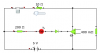
Using Laplace's circuit should do the trick. It'll light the LED as long as the devices draw 50mA or more.
For easier availability you may exchange the 1100 ohm for a 1k, and the 0.4 ohm for a 0.39 ohm w/o negative consequences.
There's virtually no other way to do it while still using standard USB chargers/ports.
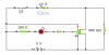
The transistor version would always drop at least 0.5V (unless you got hold of some old Germanium transistors which drop around 0.2V).
 

quioxz

Apr 16, 2010
31
Joined
Apr 16, 2010
Messages
31
Ok, thanks a lot.
But still, I can't quite get an image on how to make it yet...
I've never seen a comparator so I don't know how to put one into a circuit
But, from the LM393 datasheet, it said it can only sustain 50mA, will that be a problem?
I find it has 8 pins, 2 for power 3 for comparator A and B, sorry for asking, but how exactly do I assemble it?
If my guesses about the input V and GND are correct, it should look like my first attachment...

But then, I wonder why do I need the 270K and 1.1K resistors?
I tried to simulate it on Yenka, but it doesn't have a comparator so I use an op-amp instead and put a diode in to make it work like a comparator using this image as reference
ComparatorOPAMP.GIF

And what I made up is in attachment 2,
I only need to hook the V+ in and GND to the op amp and the 0.4ohm resistor and I checked the voltage, current of everything and it looks just fine although I loose some current to the 0.4ohm resistor
It's a 324-op amp by the way.
 

Attachments

  • image4co.jpg
    image4co.jpg
    21.7 KB · Views: 183
  • Untitled.png
    Untitled.png
    6.3 KB · Views: 170

(*steve*)

¡sǝpodᴉʇuɐ ǝɥʇ ɹɐǝɥd
Moderator
Jan 21, 2010
25,510
Joined
Jan 21, 2010
Messages
25,510
replacing the 393 with a 324 in the modelling software is probably OK. But you can't use one in practice because they come in a package with 4 of them and has more leads than the 393.

Your first attachment looks OK.

Your next step would be to test it on a solderless breadboard. If it works you can make the circuit up using veroboard.

The 0,4 ohm resistor won't cause you to lose current, it will drop some voltage (but not much).

Your attachment 2 is missing the connections to the inputs of the comparator and is powered from the wrong place in the circuit. It simply won't work.

The 270K and 1.1k resistors are required because they set a reference voltage compared with the voltage across the 0.4 ohm resistor.

That additional diode is not required, although it won't hurt anything.
 

quioxz

Apr 16, 2010
31
Joined
Apr 16, 2010
Messages
31
Ok, thanks a lot
So that means the modeling software doesn't work right?
I mean nothing exploded and the numbers are fine..
But if the 393 is ok then I'll go with it
 

(*steve*)

¡sǝpodᴉʇuɐ ǝɥʇ ɹɐǝɥd
Moderator
Jan 21, 2010
25,510
Joined
Jan 21, 2010
Messages
25,510
Well, the modelling software works OK as long as things remain within sensible ranges.

Your circuit with no inputs connected and the power supply connected across the sense resistor was not sensible.

It's a bit like complaining that a flight simulator does not correctly model what happens when an aircraft not designed for supersonic flight goes supersonic. They are designed to model the aircraft under normal conditions and it is nobody's fault if they fail to simulate correctly under conditions where the characteristics of the aircraft are uncertain and untested.
 

quioxz

Apr 16, 2010
31
Joined
Apr 16, 2010
Messages
31
So I went back and try to correct things and I still don't need the 270K and 1.1K resistors....
And the diode is probably needed because when I took it out and the switch is opened, there is like 3mA current flowing through the LED all the time
That said, depends on if my model is correct :p
 

Attachments

  • Untitled.png
    Untitled.png
    6.8 KB · Views: 174
Last edited:

(*steve*)

¡sǝpodᴉʇuɐ ǝɥʇ ɹɐǝɥd
Moderator
Jan 21, 2010
25,510
Joined
Jan 21, 2010
Messages
25,510
No, because at zero current the comparator will have the inputs equal. In theory this means that the output will be at the mid point between 0 and 5V. In practice, the comparator has errors which mean that the output could be anywhere, but most likely pinned to one supply rail or the other.

For a comparator to work it requires that the values for each input are different (this is simplifying things somewhat).

In addition for this circuit to work, the negative supply rail must be within the range of common allowable common mode voltages... (which it is)

It is good design practice to ensure that one input is held *at least* the worst case offset voltage (in this case 5mV) higher or lower than the "off" state. Since you can't make it lower than 0 volts, the suggestion was to make it slightly higher.

The resistors calculated for you gave a reference voltage of 20mV, which ensures that even with the worst case input offset the circuit will work.

Again, assuming the worst case input offset, the resistor needs to drop 25mv, which is a current of 62mA through the 0.4 ohm resistor (it could be as low as 38mA if the comparator has the opposite worst case input offset).
 

quioxz

Apr 16, 2010
31
Joined
Apr 16, 2010
Messages
31
Thanks for the info. I'll try to work it out with LM393 anyway, just out of curiosity :)
 

quioxz

Apr 16, 2010
31
Joined
Apr 16, 2010
Messages
31
Sorry for the double post, but I believe editing will notify no one that there is something new. (yeah, I need attention, lol XD)
So I've been working out with LM324 op-amp in place of the LM393 as I believe it does the same thing: allow current to pass if voltage offset on the negative sign is higher than the voltage offset on plus sign
Say, I want to save the battery better, then instead of 270K why not just make it so high the current passing will be low?
I tried 1M in place of 270K and 2K in place of 1.1K to set the reference to 10mV
Or 1M and 4K for the reference to be 20mV

I know I'm talking about a mere 10-20uA but can that be done and will it hurt and why wouldn't you do it?
Then again, why set the reference to 20mV when you can set it to just 5mV so any least sign of electric will trigger the switch in the case worse than worst?
 

(*steve*)

¡sǝpodᴉʇuɐ ǝɥʇ ɹɐǝɥd
Moderator
Jan 21, 2010
25,510
Joined
Jan 21, 2010
Messages
25,510
Sorry for the double post, but I believe editing will notify no one that there is something new. (yeah, I need attention, lol XD)

You are right on both counts :)

So I've been working out with LM324 op-amp in place of the LM393 as I believe it does the same thing: allow current to pass if voltage offset on the negative sign is higher than the voltage offset on plus sign

That's a funny way of saying it.

Essentially the output is high if the voltage on the non-inverting input (+) exceeds that of the inverting input (-). Conversely, the output is low if the voltage on the non-inverting input is lower than that of the inverting input.

Say, I want to save the battery better, then instead of 270K why not just make it so high the current passing will be low?

Considering that the devices in question draw a high current, it's probably not a huge issue.

You're using a battery? how are you regulating the voltage. That's likely to draw some current anyway (and possibly require a minimum load to remain in regulation).

I tried 1M in place of 270K and 2K in place of 1.1K to set the reference to 10mV
Or 1M and 4K for the reference to be 20mV

I know I'm talking about a mere 10-20uA but can that be done and will it hurt and why wouldn't you do it?

You then start having to consider the effect of the input current of the comparator, and leakage on the board, and if you reduce the difference you need to ensure that the comparator won't be in some in-between state and subject to noise (and possibly oscillation).

You can always try...

Then again, why set the reference to 20mV when you can set it to just 5mV so any least sign of electric will trigger the switch in the case worse than worst?

Well, mainly because it could make your circuit more sensitive to noise.

Checking again the 393 has an input offset voltage of +/- 3mv, for the 324 it's 2mV so not a huge gain.
 

quioxz

Apr 16, 2010
31
Joined
Apr 16, 2010
Messages
31
That's a funny way of saying it.

Essentially the output is high if the voltage on the non-inverting input (+) exceeds that of the inverting input (-). Conversely, the output is low if the voltage on the non-inverting input is lower than that of the inverting input.
Yeah, it's funny, and I actually thought that because I was only using switch and I never heard of it before :D

I use a 9V+7805 for regulation but I'm think about switching to AA batteries + step up since the 9V has so little mAh. But the powering section wouldn't have any effect on it (I guess).

Anyway, thanks for all the help. I'll try to gather the parts and try it out. For 0.4ohm, I guess I won't be finding it in market so I'll go with 3 1ohm in parallel.
 

(*steve*)

¡sǝpodᴉʇuɐ ǝɥʇ ɹɐǝɥd
Moderator
Jan 21, 2010
25,510
Joined
Jan 21, 2010
Messages
25,510
You should have relatively little problem getting a 0.39 ohm resistor.

If you're powering the circuit from 9 volts then you have other options to detect current, but we've gone this far, so you may as well stick to this...

Using 6xAA cells is probably a good idea if there's any significant current drawn. It's also possibly a good idea to use a regulator with low quiescent current. The quiescent current of the 7805 will dwarf the measly amount used by the 393. They require between 5 an 8 mA.
 

quioxz

Apr 16, 2010
31
Joined
Apr 16, 2010
Messages
31
Actually, I was thinking of 2AAs + step up converter or sort of that
The quiescent would probably be lower than 1mA too and my power would be pretty much limited
 

(*steve*)

¡sǝpodᴉʇuɐ ǝɥʇ ɹɐǝɥd
Moderator
Jan 21, 2010
25,510
Joined
Jan 21, 2010
Messages
25,510
2xAA and a switchmode (or worse switched capacitor) circuit to increase the voltage is going to impose a really impressive load on the AA batteries.

Consider that 2xAA batteries are not much larger than a single 9V battery. The amount of energy they hold will be similar.

Whilst using a boost circuit from 3V to generate 5 is probably more efficient than using a linear regulator to produce 5 from 9, there are many other drawbacks.

Neither your original circuit, nor your response to questions about your specific requirements mentioned the 9V battery (in fact you implied the power source was a PC USB port or something similar). Aside from the fact that we would have made comments about the use of a 9 volt battery, it essentially means that the advice we've given you about the series resistor and the comparator are (at best) a poor solution to your problem.

Do you want to start again?
 

quioxz

Apr 16, 2010
31
Joined
Apr 16, 2010
Messages
31
Haha,
well, regular 9V holds about 400-500mAh
regular alkaline AA battery range from roughly 1500-3000mAh.
It's a huge different :)

I didn't mention the power source because I wasn't able to decide what to use..
I could have gone with some bigger batteries(3.7V LiPoly?) in series and use a linear regulator or with just a few small batteries with a booster
Btw, for 500mA draw, I probably use 3 rechargeable AAs instead of normal 2 AA and even with voltage drop, it will still be around 3V
 

(*steve*)

¡sǝpodᴉʇuɐ ǝɥʇ ɹɐǝɥd
Moderator
Jan 21, 2010
25,510
Joined
Jan 21, 2010
Messages
25,510
actually if you multiply the voltage by the mAh rating to get an idea of mWh, you'll find a different relationship.

9V battery: 3600 to 4500 mWh

1.5V cell: 2250 to 4500 mWh

For high current, you would be far better off looking at placing AA cells in parallel or considering a larger cell size (C or even D).

A "booster" is not the trivial thing you think it is.

LiPo batteries are not always bigger and they are very intolerant of being used outside their specified charge and discharge limits (intolerant = smoke and flames)

Other battery technologies are more tolerant of abuse.

If you're really thinking of a "booster" then you should be thinking of a buck regulator where your battery voltage is > 5V. But these are not simple 3 terminal devices like the 7805 and have their own share of design issues.
 

quioxz

Apr 16, 2010
31
Joined
Apr 16, 2010
Messages
31
Suppose I say the device draws constant 500mA, not taking into calculation the power required for LM393, LED, pull ups, etc.
A 9V battery with 500mAh would be dead in 1 hour (assuming no voltage drop and the regulator works all the way through, which wouldn't happen)
For 3 recharge able cell, given they provide 1.2V each.
Pout = Pin * eff (eff = 0.8)
So,
Iout * Vout = Iin * Vin * 0.8
Iin = Iout * Vout / (Vin * 0.8)
Iout = 500mA, Vout = 5V, Vin = 3*1.2 = 3.6V
Iin = 0.5*5/(3.6*0.8) = roughly 868mA
So a cell with approx 2000mAh would last at least 2 hours, again assuming no voltage drop
I'm thinking about a Ni-MH rechargeable ones, probably the most ideal for the job (I think? :D)
Anyway 9V is too much and any voltage drop would be power drop, I'm loosing 4V*500mAh = 2000mWh to do something else in the circuit or heat
So the device wouldn't benefit from all the 4500mWh in the 9V

And I'm too afraid to put batteries in parallel :p
Larger cell size wouldn't be an option since I have to box it and I don't like the idea of sticking the battery rails outside my box :D
Just want it to look nice
 
Last edited:

55pilot

Feb 23, 2010
434
Joined
Feb 23, 2010
Messages
434
And I'm too afraid to put batteries in parallel :p
Smart move. You should NEVER be putting batteries in parallel without appropriate load balancing and back-drive prevention circuits.

---55p
 

55pilot

Feb 23, 2010
434
Joined
Feb 23, 2010
Messages
434
Suppose I say the device draws constant 500mA, not taking into calculation the power required for LM393, LED, pull ups, etc.
A 9V battery with 500mAh would be dead in 1 hour (assuming no voltage drop and the regulator works all the way through, which wouldn't happen)
It has absolutely no hope of lasting that long. The mAh rating is given for when the battery is drained over several hours and is specified in the spec.

The typical 9V battery capacity is specified for when the battery is driving a 100 ohm load. That starts with a 90mA current and gradually decreases to 55mA at the cutoff voltage of 5.5V. That setup typically lasts for 6 hours. When you drain the same battery at 500mA, expect to see less than 45 minutes of life out of it.

---55p
 

(*steve*)

¡sǝpodᴉʇuɐ ǝɥʇ ɹɐǝɥd
Moderator
Jan 21, 2010
25,510
Joined
Jan 21, 2010
Messages
25,510
Smart move. You should NEVER be putting batteries in parallel without appropriate load balancing and back-drive prevention circuits.

Unless you're looking at non-rechargable AA cells, in which case you'll be pretty safe (and that was what I assumed he was talking about).

I agree for rechargeable batteries.

Actually, putting rechargeable batteries in series is almost as bad.

For your circuit, my approach would be to use a higher voltage battery and a buck regulator in preference to a lower battery voltage and a boost regulator. But that's just a preference, not any sort of hard rule.

I guess we have to ask again. Exactly what is this for? Your earlier explanation lacked specificity. You want to charge stuff, apparently from a portable power source. What is it? What are the power requirements? And what are the dimensions of this box that you've designed before you designed the power supply to go inside it?
 
Last edited:
Top