so I think the code is fine, I should use the LM3914 and the pwm pins of the esp32 dev board (there are 16) each pin to represent a column and band width and set the max signal of the LM3914to 5V so that means that when the signal is at 5v, all the LED's in that column would lit. so I have this code and it compiled fine for the esp32 dev board and I'm
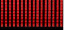
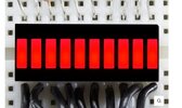
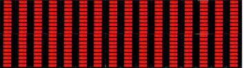
not using WS2812B LED strip, I am using bar graph type LED's, can you help me modify the code for my needs and explain please!? with 16 columns and 20 rows (instead of 30) thats 320 LED's! but I need the bar graph type because I want a certain "look", thank you! also I can change the amplitude to make the columbs go up to the desired 20 LED's
So I would set LM3914 for 5V all LEDs on.
So thats max V we want out of filter
20 leds will light in each band? when the pwm signal is 5v
// (Heavily) adapted from
https://github.com/G6EJD/ESP32-8266-Audio-Spectrum-Display/blob/master/ESP32_Spectrum_Display_02.ino
// Adjusted to allow brightness changes on press+hold, Auto-cycle for 3 button presses within 2 seconds
// Edited to add Neomatrix support for easier compatibility with different layouts.
#include <FastLED_NeoMatrix.h>
#include <arduinoFFT.h>
#include <EasyButton.h>
#define SAMPLES 1024 // Must be a power of 2
#define SAMPLING_FREQ 40000 // Hz, must be 40000 or less due to ADC conversion time. Determines maximum frequency that can be analysed by the FFT Fmax=sampleF/2.
#define AMPLITUDE 1000 // Depending on your audio source level, you may need to alter this value. Can be used as a 'sensitivity' control.
#define AUDIO_IN_PIN 35 // Signal in on this pin
#define LED_PIN 5 // LED strip data
#define BTN_PIN 4 // Connect a push button to this pin to change patterns
#define LONG_PRESS_MS 200 // Number of ms to count as a long press
#define COLOR_ORDER GRB // If colours look wrong, play with this
#define CHIPSET WS2812B // LED strip type
#define MAX_MILLIAMPS 2000 // Careful with the amount of power here if running off USB port
const int BRIGHTNESS_SETTINGS[3] = {5, 70, 200}; // 3 Integer array for 3 brightness settings (based on pressing+holding BTN_PIN)
#define LED_VOLTS 5 // Usually 5 or 12
#define NUM_BANDS 16 // To change this, you will need to change the bunch of if statements describing the mapping from bins to bands
#define NOISE 500 // Used as a crude noise filter, values below this are ignored
const uint8_t kMatrixWidth = 16; // Matrix width
const uint8_t kMatrixHeight = 16; // Matrix height
#define NUM_LEDS (kMatrixWidth * kMatrixHeight) // Total number of LEDs
#define BAR_WIDTH (kMatrixWidth / (NUM_BANDS - 1)) // If width >= 8 light 1 LED width per bar, >= 16 light 2 LEDs width bar etc
#define TOP (kMatrixHeight - 0) // Don't allow the bars to go offscreen
#define SERPENTINE true // Set to false if you're LEDS are connected end to end, true if serpentine
// Sampling and FFT stuff
unsigned int sampling_period_us;
byte peak[] = {0,0,0,0,0,0,0,0,0,0,0,0,0,0,0,0}; // The length of these arrays must be >= NUM_BANDS
int oldBarHeights[] = {0,0,0,0,0,0,0,0,0,0,0,0,0,0,0,0};
int bandValues[] = {0,0,0,0,0,0,0,0,0,0,0,0,0,0,0,0};
double vReal[SAMPLES];
double vImag[SAMPLES];
unsigned long newTime;
arduinoFFT FFT = arduinoFFT(vReal, vImag, SAMPLES, SAMPLING_FREQ);
// Button stuff
int buttonPushCounter = 0;
bool autoChangePatterns = false;
EasyButton modeBtn(BTN_PIN);
// FastLED stuff
CRGB leds[NUM_LEDS];
DEFINE_GRADIENT_PALETTE( purple_gp ) {
0, 0, 212, 255, //blue
255, 179, 0, 255 }; //purple
DEFINE_GRADIENT_PALETTE( outrun_gp ) {
0, 141, 0, 100, //purple
127, 255, 192, 0, //yellow
255, 0, 5, 255 }; //blue
DEFINE_GRADIENT_PALETTE( greenblue_gp ) {
0, 0, 255, 60, //green
64, 0, 236, 255, //cyan
128, 0, 5, 255, //blue
192, 0, 236, 255, //cyan
255, 0, 255, 60 }; //green
DEFINE_GRADIENT_PALETTE( redyellow_gp ) {
0, 200, 200, 200, //white
64, 255, 218, 0, //yellow
128, 231, 0, 0, //red
192, 255, 218, 0, //yellow
255, 200, 200, 200 }; //white
CRGBPalette16 purplePal = purple_gp;
CRGBPalette16 outrunPal = outrun_gp;
CRGBPalette16 greenbluePal = greenblue_gp;
CRGBPalette16 heatPal = redyellow_gp;
uint8_t colorTimer = 0;
// FastLED_NeoMaxtrix - see
https://github.com/marcmerlin/FastLED_NeoMatrix for Tiled Matrixes, Zig-Zag and so forth
FastLED_NeoMatrix *matrix = new FastLED_NeoMatrix(leds, kMatrixWidth, kMatrixHeight,
NEO_MATRIX_TOP + NEO_MATRIX_LEFT +
NEO_MATRIX_ROWS + NEO_MATRIX_ZIGZAG +
NEO_TILE_TOP + NEO_TILE_LEFT + NEO_TILE_ROWS);
void setup() {
Serial.begin(115200);
FastLED.addLeds<CHIPSET, LED_PIN, COLOR_ORDER>(leds, NUM_LEDS).setCorrection(TypicalSMD5050);
FastLED.setMaxPowerInVoltsAndMilliamps(LED_VOLTS, MAX_MILLIAMPS);
FastLED.setBrightness(BRIGHTNESS_SETTINGS[1]);
FastLED.clear();
modeBtn.begin();
modeBtn.onPressed(changeMode);
modeBtn.onPressedFor(LONG_PRESS_MS, brightnessButton);
modeBtn.onSequence(3, 2000, startAutoMode);
modeBtn.onSequence(5, 2000, brightnessOff);
sampling_period_us = round(1000000 * (1.0 / SAMPLING_FREQ));
}
void changeMode() {
Serial.println("Button pressed");
if (FastLED.getBrightness() == 0) FastLED.setBrightness(BRIGHTNESS_SETTINGS[0]); //Re-enable if lights are "off"
autoChangePatterns = false;
buttonPushCounter = (buttonPushCounter + 1) % 6;
}
void startAutoMode() {
autoChangePatterns = true;
}
void brightnessButton() {
if (FastLED.getBrightness() == BRIGHTNESS_SETTINGS[2]) FastLED.setBrightness(BRIGHTNESS_SETTINGS[0]);
else if (FastLED.getBrightness() == BRIGHTNESS_SETTINGS[0]) FastLED.setBrightness(BRIGHTNESS_SETTINGS[1]);
else if (FastLED.getBrightness() == BRIGHTNESS_SETTINGS[1]) FastLED.setBrightness(BRIGHTNESS_SETTINGS[2]);
else if (FastLED.getBrightness() == 0) FastLED.setBrightness(BRIGHTNESS_SETTINGS[0]); //Re-enable if lights are "off"
}
void brightnessOff(){
FastLED.setBrightness(0); //Lights out
}
void loop() {
// Don't clear screen if waterfall pattern, be sure to change this is you change the patterns / order
if (buttonPushCounter != 5) FastLED.clear();
modeBtn.read();
// Reset bandValues[]
for (int i = 0; i<NUM_BANDS; i++){
bandValues
= 0;
}
// Sample the audio pin
for (int i = 0; i < SAMPLES; i++) {
newTime = micros();
vReal = analogRead(AUDIO_IN_PIN); // A conversion takes about 9.7uS on an ESP32
vImag = 0;
while ((micros() - newTime) < sampling_period_us) { /* chill */ }
}
// Compute FFT
FFT.DCRemoval();
FFT.Windowing(FFT_WIN_TYP_HAMMING, FFT_FORWARD);
FFT.Compute(FFT_FORWARD);
FFT.ComplexToMagnitude();
// Analyse FFT results
for (int i = 2; i < (SAMPLES/2); i++){ // Don't use sample 0 and only first SAMPLES/2 are usable. Each array element represents a frequency bin and its value the amplitude.
if (vReal > NOISE) { // Add a crude noise filter
/*8 bands, 12kHz top band
if (i<=3 ) bandValues[0] += (int)vReal;
if (i>3 && i<=6 ) bandValues[1] += (int)vReal;
if (i>6 && i<=13 ) bandValues[2] += (int)vReal;
if (i>13 && i<=27 ) bandValues[3] += (int)vReal;
if (i>27 && i<=55 ) bandValues[4] += (int)vReal;
if (i>55 && i<=112) bandValues[5] += (int)vReal;
if (i>112 && i<=229) bandValues[6] += (int)vReal;
if (i>229 ) bandValues[7] += (int)vReal;*/
//16 bands, 12kHz top band
if (i<=2 ) bandValues[0] += (int)vReal;
if (i>2 && i<=3 ) bandValues[1] += (int)vReal;
if (i>3 && i<=5 ) bandValues[2] += (int)vReal;
if (i>5 && i<=7 ) bandValues[3] += (int)vReal;
if (i>7 && i<=9 ) bandValues[4] += (int)vReal;
if (i>9 && i<=13 ) bandValues[5] += (int)vReal;
if (i>13 && i<=18 ) bandValues[6] += (int)vReal;
if (i>18 && i<=25 ) bandValues[7] += (int)vReal;
if (i>25 && i<=36 ) bandValues[8] += (int)vReal;
if (i>36 && i<=50 ) bandValues[9] += (int)vReal;
if (i>50 && i<=69 ) bandValues[10] += (int)vReal;
if (i>69 && i<=97 ) bandValues[11] += (int)vReal;
if (i>97 && i<=135) bandValues[12] += (int)vReal;
if (i>135 && i<=189) bandValues[13] += (int)vReal;
if (i>189 && i<=264) bandValues[14] += (int)vReal;
if (i>264 ) bandValues[15] += (int)vReal;
}
}
// Process the FFT data into bar heights
for (byte band = 0; band < NUM_BANDS; band++) {
// Scale the bars for the display
int barHeight = bandValues[band] / AMPLITUDE;
if (barHeight > TOP) barHeight = TOP;
// Small amount of averaging between frames
barHeight = ((oldBarHeights[band] * 1) + barHeight) / 2;
// Move peak up
if (barHeight > peak[band]) {
peak[band] = min(TOP, barHeight);
}
// Draw bars
switch (buttonPushCounter) {
case 0:
rainbowBars(band, barHeight);
break;
case 1:
// No bars on this one
break;
case 2:
purpleBars(band, barHeight);
break;
case 3:
centerBars(band, barHeight);
break;
case 4:
changingBars(band, barHeight);
break;
case 5:
waterfall(band);
break;
}
// Draw peaks
switch (buttonPushCounter) {
case 0:
whitePeak(band);
break;
case 1:
outrunPeak(band);
break;
case 2:
whitePeak(band);
break;
case 3:
// No peaks
break;
case 4:
// No peaks
break;
case 5:
// No peaks
break;
}
// Save oldBarHeights for averaging later
oldBarHeights[band] = barHeight;
}
// Decay peak
EVERY_N_MILLISECONDS(60) {
for (byte band = 0; band < NUM_BANDS; band++)
if (peak[band] > 0) peak[band] -= 1;
colorTimer++;
}
// Used in some of the patterns
EVERY_N_MILLISECONDS(10) {
colorTimer++;
}
EVERY_N_SECONDS(10) {
if (autoChangePatterns) buttonPushCounter = (buttonPushCounter + 1) % 6;
}
FastLED.show();
}
// PATTERNS BELOW //
void rainbowBars(int band, int barHeight) {
int xStart = BAR_WIDTH * band;
for (int x = xStart; x < xStart + BAR_WIDTH; x++) {
for (int y = TOP; y >= TOP - barHeight; y--) {
matrix->drawPixel(x, y, CHSV((x / BAR_WIDTH) * (255 / NUM_BANDS), 255, 255));
}
}
}
void purpleBars(int band, int barHeight) {
int xStart = BAR_WIDTH * band;
for (int x = xStart; x < xStart + BAR_WIDTH; x++) {
for (int y = TOP; y >= TOP - barHeight; y--) {
matrix->drawPixel(x, y, ColorFromPalette(purplePal, y * (255 / (barHeight + 1))));
}
}
}
void changingBars(int band, int barHeight) {
int xStart = BAR_WIDTH * band;
for (int x = xStart; x < xStart + BAR_WIDTH; x++) {
for (int y = TOP; y >= TOP - barHeight; y--) {
matrix->drawPixel(x, y, CHSV(y * (255 / kMatrixHeight) + colorTimer, 255, 255));
}
}
}
void centerBars(int band, int barHeight) {
int xStart = BAR_WIDTH * band;
for (int x = xStart; x < xStart + BAR_WIDTH; x++) {
if (barHeight % 2 == 0) barHeight--;
int yStart = ((kMatrixHeight - barHeight) / 2 );
for (int y = yStart; y <= (yStart + barHeight); y++) {
int colorIndex = constrain((y - yStart) * (255 / barHeight), 0, 255);
matrix->drawPixel(x, y, ColorFromPalette(heatPal, colorIndex));
}
}
}
void whitePeak(int band) {
int xStart = BAR_WIDTH * band;
int peakHeight = TOP - peak[band] - 1;
for (int x = xStart; x < xStart + BAR_WIDTH; x++) {
matrix->drawPixel(x, peakHeight, CHSV(0,0,255));
}
}
void outrunPeak(int band) {
int xStart = BAR_WIDTH * band;
int peakHeight = TOP - peak[band] - 1;
for (int x = xStart; x < xStart + BAR_WIDTH; x++) {
matrix->drawPixel(x, peakHeight, ColorFromPalette(outrunPal, peakHeight * (255 / kMatrixHeight)));
}
}
void waterfall(int band) {
int xStart = BAR_WIDTH * band;
double highestBandValue = 60000; // Set this to calibrate your waterfall
// Draw bottom line
for (int x = xStart; x < xStart + BAR_WIDTH; x++) {
matrix->drawPixel(x, 0, CHSV(constrain(map(bandValues[band],0,highestBandValue,160,0),0,160), 255, 255));
}
// Move screen up starting at 2nd row from top
if (band == NUM_BANDS - 1){
for (int y = kMatrixHeight - 2; y >= 0; y--) {
for (int x = 0; x < kMatrixWidth; x++) {
int pixelIndexY = matrix->XY(x, y + 1);
int pixelIndex = matrix->XY(x, y);
leds[pixelIndexY] = leds[pixelIndex];
}
}
}
}


 tools.analog.com
 github.com