Sir Cirkit . . . . .
We have definitely met B-4 . . . with my remembering, when I zeroed in on your Gravatars IBM discrete component circuit card from
the late 1950's into1960's used in the
IBM SMS Mainframe, with that one 2N404 transistor sporting a code date 33 week of 1960.
To wit . . . . .IBM DISCRETE DESIGN CIRCUIT CARDS
IBM SMS card database, describing the Standard Modular System cards used in 1960s mainframe computers.
static.righto.com
So o o o o o o o this post now has 180+ reads and
¿ WHY? has no one caught the 40 into 42 pins will not go . .
subliety aspect?
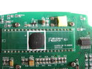
Specifically . . . . . the datasheet IC has 42 pins while your PCB only has 40 pins ???.
PLUS . . . . . if you look at the photo of the small portion of the whole PCB that you show, the Chip On Board
under the BLACK epoxy blob, is on a daughter board that sits upon the main TWO sided board.
THE JRC APPLICATION NOTE . . . . . COMPARISONS . . . . . . TO YOUR PCB FOIL LAYOUT
Referring to the application note of the
JRC top schema that uses the 9V battery power source.
It is giving the correct pin outs for the NJU9203
BM suffix standard 42 thru hole mounting pins.
Since your unit is showing the use of 40 pins upon a daughter board, we need to use the pin numbering
protocol as is used for the gull wing surface mount version which is a NJU9203BD . If you are unfamiliar with
gulls leads, look nearby, to the right at the
CMOS HEP4030 and its pins.
(Your board is showing an obscured
Chip On Board black epoxy blob covering up the actual semi chip, and it
looks like its foils make interconnects the same as the
BD suffix does.)
I see that chip to be having 12 connections coming out its top side and tieing into foil runs that connect
into associative pins on the same daughter board thru board pins. Likewise for the 10 connections on the
right side, then there is the bottom side but with only 11 connections, with there being a final variant where ONLY 7 pins on the far left side are being foil runs, being a set of 5 and then up to a skipped trace space and a final pair of traces.
Now, my
HIGHLY EDUCATED estimation, is that nearby 4030 CMOS logic chip is being utilized as a driver for the inter digit
decimal points on the display and are being switched between, in accordance as to what position /range that
the central rotary knob is in, as being respective to its assigned one rotary ring and its sets of radial contacts
associated with the knob pointers range.
You will find the correct pin assignment of your NJU9203
BD on my supplied left illustration.
NOTICE that its
NOT the 42 pin BM version on the right such as is being used on the APPLICATION NOTE schematic just above
it.
The 99203
BD I.C. solely dedicates its pins 2-19 to sets of 7 segment display, pin20 for polarity indicator and
finally interconnects and pins 21-25 to the last of the 7 segment display connections.
Something fishy below ?
Referring to your PCB pins, 1-11 have a myriad of components mounted just below those pins and then pins
12 -20 even are having a full solid ground plane placed just under them .
Jump up to pins 23-27 and the presence of components placed just above them is equally as confusing.
Back to the application note, but this time look at page 5-4 and the LEFT IC pin assignment that has your units
40 pins. as being.
Pins 2-19 account for display drive
Pins 21-25 provide individual digit drives
The real ancillary related support components of the chip are being associated with pins 26-40.
I can account for every pin.
Pin 26 9V Battery Negative terminal
Pin 27-28-29 are used for an Auto Zero / Phase Buffer C-R-C network
Pin 30 Meter - analog ground
Pin 31 Meter + analog input
Pin 32 Analog Ground
Pin 33-34 Capacitor
Pin 35 9V Battery Positive terminal
Pin 36 Vol Ref High Set
Pin 37 TEST
Pin 38-39-40 Osc R- C time constants network
and finally . . .
Pin 1 is connected to a High logic level to latch onto /or/ unlatch from the HOLD meter data function. (Or as perceived later on.)
FOLLOW THE LEADER . . . . or . . . DO AS I WOULD DO . . .
My first thing to check would be the battery connector . . .the male stud portion will be is as steady as a rock
on both the battery proper and its mating battery connector, just by virtue of their mechanical design.
HOWEVER!
The female receptor with its 4 springy-dingy compression contacts . . . . which are subject to tensile "loss of
memory" and their stretching outward and loosening or even loosing contact /or/ having intermittence of contact
with its mating stud contact.
Considering that within this units 2004 time of design until present 2024 . . . .and that this unit has been a
daily . . . or at least weekly user . . . . just imagine how many 9V batteries have mated into and out of those
contact pairs !
Sooooooooooooooooo . . . .next, confirm the gripping integrity of those two battery contacts.
Next in line would be inspecting the two stranded wires that connect between the battery connector and the
meters PCB.
Now, could repeated wire flexes, in process of battery changing, resulted in metal fatigue and a broken wire set
hidden underneath wire insulation ?
Use another meter to OHM out and check out total lead continuity of both
battery connections, with a final reading taken with those wire leads being tensioned, twisted and steadily tugged upon.
DEDICATED FUNCTION CLUSTER BUILDUPS
Will be found around the board and switched in by the main function / Range knob to interface into the DC
200mv input of that voltmeter chip.
Looking at the knobs settings I see the need for :
1. A series string of decade resistors for the DC millivolt and voltage measuring function.
2. A series string of decade current shunt resistors for the DC current measuring function.
3. A precision rectifier circuit to convert AC to corrected DC for the AC voltage and current ranges.
4. A constant current source and switched range decade resistors for the ohmmeter function
of the meter that is fed into the 200mv DC volt range of the unit.
5 The DIODE test function will receive a precise constant current , with the resultant voltage across the diode being read out as a DC voltage of the DC voltage function of the meter.
6. The continuity test aspect /range will be monitored by probes so that low ohms threshold(s) will be detected and fed to a piezo transducers aural alert.
7. The BLACK Data hold push button is routing a high logic to pin one of the NJU9303BD.
*****
8. GREEN main power switch.
***** After / if ever . . . . getting an operative display you will want to test pin 1 voltage to see if the high logic level drops to a low level after you release its BLACK button . If so the latch / unlatch function is being produced within the 9303 main chip. If not, and then relies upon another push of the BLACK button, the latch action is being performed by a separate and dedicated component function / cluster somewhere on the PCB. Just track down the area that pin 1 foil goes to.
. . . . . . . . . . MY AMASSED / and / UNITIZED REFERENCING ILLUSTRATIONS . . . . . . . . . . .
INITIAL TROUBLESHOOTING PROCEDURAL . . . . .
Will be on function 8, where you need another meter to do a voltage or OHMS test . . .your option.
See if there is solid continuity from respective battery terminal contacts to their connections on pins 26 and 36.
MYSELF ? I f testing good, I would even go so far as to test on down the micro foil traces at end where they are finally covered with an epoxy junction. I'd be holding a single edge razor blade into a probe and piercing the foil/epoxy diverture with a blade corner.
Before or by this time you need to see if the + 9 V supply line was routed into a mentioned component cluster
that does the switch latch on / latch off functtion, in response to a single press of that momentary contact power switch.
I
NFORMATION . . . time out . . . . . . for getting feed back or any procedural questions from you. . . . and letting the members of the viewing peanut gallery take a biss preak !
RE . . .
You can look at data lines to see if the LCD is being muxed. . . . . . . .as in multiplexed
Let me know the instant that you can get a display showing on that unit . . . . .for a functional
EARTH SHATTERING test procedure.
Pee Ess . . . .
Will be needing to see all of the bottom, yet unseen, portion of that PCB to isolate those "function clusters" with the
On-Off probably being the first of interest . . . . .after / if you see pin pin 33 /or/ battery + running to an area.
73's de Edd . . . . . .
I just done went and experienced myself a gender change, early morning today . . . . . . of course, it not being on purpose .
It's just being that DANG COLD outside ! . . . . . "everything" just pulled themselves inside . . . . .
TRYING! to keep warm.
.
")