But now the fastest linear actuators who reaches its in/out position first only stops when the slowest linear actuators reach the max position.
Why would that be so? If every actuator has its own set of limit switches, as shown in your diagram, there is no reason why the fastest actuator should have to wait for the slowest on to stop.
With the switch positions as shown in the diagram, all actuators have reached the
in position, the
in limit switches are open, the actuators are stopped. K1 is in the
in position, but since the limit switches are open, no current flows, everything is idle.
When you now toggle K1, current will flow through the
out limit switches, which are closed. The direction of the current is reversed by K1, therefore the actuators will start movin in th eopposite direction. When an actuator hits the associated
out limit switch, the switch will open and the actuator will stop. The other actuators, not havng reached their end positions, will contine to operate until each has hit his own
out limit switch.
Your schematic looks good. Unless your real world setup differs from your schematic, I see no reason why this should not work as expected.
Scratch head, think, scratch, think,.....
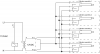
I think I see the problem: Th issue is with the opposite limit switches, in this case the
in ones. Check this annotated diagram:

The
in limit switches will close once the actuators have left their end positions. Being connected as they are, they allow current to flow from the
out switches back to the other actuators. Therefore the system will stop only with the last actuator in the end position.
You can prevent this current flow by cutting the connections (green slanted cut through blue wire) and adding new connections with diodes as shown. Current can flow from the out switch back to the common connection (anodes of the diodes and K1.1), but from there on not forward to the other actuators as the other diodes are in reverse.
Of course you'll have to repeat the same for the wires going to the
out switches, this time with the diodes reversed (as the polarity of the current is reversed in that direction. I leave this as an exercise to you
")
.