.
Sir looxuser . . . . .
Looks like your 13 Meggle-hurtz of compressed data has just now, finally made it down the pipeline .
I now see that you must have a $ Kilobuck $ system if being totally complete.
The separation of all of the different stacked units would make it hard to work on, IF they just have small short length custom flat cabling interconneting between the different units.
BUT . . . the main power unit seems to have all of the control that we will initially need.
And that unit will be the primary one of interest, since it has the Audio Output Amp circuitry in it.
The backs of the units seem to have ~ 10 wire separate interconnecting custom flat cable daisy chained between them and some
of them are depending upon +12VDC and some power from a lower level AC voltage supplied by two of the connections from the
AC supply, incoming from the PT1 power transformer in the main unit.
The first questiion now, is if this is your unit /system from day and that you are completely familiar with it and have been using it for years and it just stopped working now ? . . . . . Answer.
OR is this something new to you /used and possibly not even working to begin with, and you COULD be fooled by a simple switch or function being in a wrong position, like tape position, or in monitor position or even a control mis setting related to all of the complexity added by the Dolby, and Surrouind Sound aspects of the unit versus direct (bypassed) ?. . . . Answer.
You mentioned hearing a febble FM/AM tuner sound, as well as the mike input lighting up the scales of the Equalizer display.
But as I said, in order to troubleshoot the main unit and therewith, have its top and bottom covers off for access
/and/readings, any use of the other Tuner and Eq units seems unlikely* . . .am I right ? ( * Due to the short 10 connection custom
flat cable being used . . . . . Answer
You say:
" I see that IC604 (Functional attenuator) seems to take digital signals from the front panel to drive the actions of functional switching IC's 601 & 602."
Yes, your units design uses a continuous and updating series digital stream for control functions, or in a few cases of MC4051 or MC 4052 CMOS being used in switching cases , they just use a logic lo/hi from the u/p to toggle their states.
Now, surely I can't expect you to pull out a HP combined audio osc and dist analyzer, along with a companion Tek or Hoooolet
Plastered triggered scope . . . . . so this testing technique will be utilizing KISS and Mac Guyver technology, for your convenience / test equipment deficiencies..
So the game plan is to troubleshoot by signal injection in either using some of the multiplexed "whine" generated by the IC151
microprocessor , or solder tack together a voltage divider and impedance matching network to use the VAC feeding between the
units, or the use of a VCR or CD player that we can tap off its output audio with use of a shielded patch cord with RCA connectors and use anywhere from a .01 thru 1 ufd poly or ceraamic capacitor for DC blocking and AC coupling into the amp.
Now answers pls . . . . as well as your possibly having the simplest good audio source, as was just mentioned in the very last option.
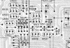
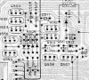
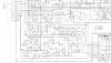
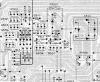
I placed the primary info that we will be consulting in the attached mark up.
The STK power amp is on the far right since the schematic was erroneously designating pin 8 as one of its inputs . . . . which is
supposed to be 18 and now is properly marked on the block diagram.
Also, I "flipped" some of the switches to the proper positions that we will be working with.
Starting at the left GREEN arrow, it is showing one channels tuner audio path taken all the way to the input of the STK AF power module.
Talk to me and fill me in on the ?'s.
Tech Ref : (Clickee-Clickee)
Dat unit . . . . itsalookalikeadis . . . . . on its
frontal knobs and buttons markings:
73's de Edd
.