Krishnasastry
- Sep 25, 2019
- 5
- Joined
- Sep 25, 2019
- Messages
- 5
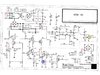
HI
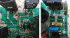
I had purchased a TreadMill having a the control board TD-700 V1.2. While my son
was using, the varistor (top left, green shaded) blew-up. Although I replaced the same
but the machine is not starting (not even the relay engaging).
Components replaced:
After this I suspected some component burns (not visible to naked eye)., I replaced
the fast rectifier FEP30JP and the Toshiba GT60M303 (replaced with an equivalent).
I suppose the rectifier BG2 BR356J is working based on elementary, multimeter
based testing by me (I am not an expert but tried to test after watching the youtube videos). I have also replaced the 470 uF 400V large Electrolyte capacitor. I have also replaced two 470uF 36V EC1 and EC2.
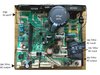
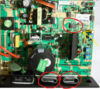
Two unmarked components:
There are two components transistors yellow (NPN), and blue (PNP) for which the
component labels were erased. Yes the components were 'filed' to remove the markings. Based on the diagram I suppose there are regular transistors (not sure why the markings were erased).
I am not seeing anything else burned or visibly damaged. Right now the instrument
powers but does not start.
Motor related:
My motor (HN1010B), 2HP, 230V, RPM4000 motor works very nice. I mean I have connected my LIPO battery as well as my 36V cordless drill battery and the motor spins well including the belt (no friction or bearing issues). In addition, if I short the terminals with fork, it is very hard to spin it. So I suppose there is no issue with it.
My speed sensor is also working well.
I have seen the same TD-700, TD-350 or TD-1600 board repairs in forums but all trails went
dead as people have either disposed of their machines or lost interest. I still like this machine as it working well. I want to make a last ditch effort before I replace the whole control board with another generic controller.
Can someone please help me to get going.
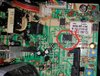
I had purchased a TreadMill having a the control board TD-700 V1.2. While my son
was using, the varistor (top left, green shaded) blew-up. Although I replaced the same
but the machine is not starting (not even the relay engaging).
Components replaced:
After this I suspected some component burns (not visible to naked eye)., I replaced
the fast rectifier FEP30JP and the Toshiba GT60M303 (replaced with an equivalent).
I suppose the rectifier BG2 BR356J is working based on elementary, multimeter
based testing by me (I am not an expert but tried to test after watching the youtube videos). I have also replaced the 470 uF 400V large Electrolyte capacitor. I have also replaced two 470uF 36V EC1 and EC2.
Two unmarked components:
There are two components transistors yellow (NPN), and blue (PNP) for which the
component labels were erased. Yes the components were 'filed' to remove the markings. Based on the diagram I suppose there are regular transistors (not sure why the markings were erased).
I am not seeing anything else burned or visibly damaged. Right now the instrument
powers but does not start.
Motor related:
My motor (HN1010B), 2HP, 230V, RPM4000 motor works very nice. I mean I have connected my LIPO battery as well as my 36V cordless drill battery and the motor spins well including the belt (no friction or bearing issues). In addition, if I short the terminals with fork, it is very hard to spin it. So I suppose there is no issue with it.
My speed sensor is also working well.
I have seen the same TD-700, TD-350 or TD-1600 board repairs in forums but all trails went
dead as people have either disposed of their machines or lost interest. I still like this machine as it working well. I want to make a last ditch effort before I replace the whole control board with another generic controller.
Can someone please help me to get going.