Maker Pro
Maker Pro

Simple UA741 and 2N3392 circuit troubleshooting

roboDNA

Jul 22, 2022
9
Joined
Jul 22, 2022
Messages
9
Hi,

I'm learning how to use the UA741CP together with a 2N3392 to get a -5V voltage source.

For some reason, when I breadboard the components, I get 0.60V instead of the expected -5V.

I have created a Falstad circuit simulation and it does work, but my breadboard version does not.

I have checked the resistor values, and pin assignments many times and they seem ok. I tried swapping out the 741 and 2N3392.

Any ideas on what I could be doing wrong?

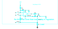
Here is the simulation:


Thank you!
 

crutschow

May 7, 2021
853
Joined
May 7, 2021
Messages
853
Don't see how it can work with no negative voltage source to the transistor emitter.
How do you expect the emitter to go negative without that?
Try adding a 1kΩ resistor from the emitter to -10V.
 

Sunnysky

Jul 15, 2016
541
Joined
Jul 15, 2016
Messages
541
The problem using an NPN with any load towards 0V raises the voltage as Vbe is reverse biased. Using a PNP emitter out instead will sink current.
 

roboDNA

Jul 22, 2022
9
Joined
Jul 22, 2022
Messages
9
Thanks for the info. I'm looking into this now. I was under the impression the - input of the opamp would be at -5V since the + input is at -5V, since the opamp would be attempting to make those 2 inputs equal... and that is where the -5v would originate from...

I'm also curious to discover why my original Falstad simulation worked, showing -5V. I'll report back when I made headway.
 

Harald Kapp

Moderator
Moderator
Nov 17, 2011
13,747
Joined
Nov 17, 2011
Messages
13,747
and that is where the -5v would originate from...
You're right in assuming the opamp will try to match the voltages at the + and - inputs. However, there has to be a source for that voltage to come from. In your circuit the only source driving the - input is the NPN transistor which can pull up to near 0 V but not down to -5 V. Try a load resistor, e.g. 1 k, from the emitter of the NPN transistor to -10 V. This provides a path for regulation of the node at the emitter to .-5 V via the opamp.
This load resistor is the answer in @Sunnysky solution provided in post #4, lower image.

That you see -5 V in your simulation may be a simulation artefact depending on how the model for the opamp is constructed internally. I see the same effect using another simulator, namely LTSPICE.
 

roboDNA

Jul 22, 2022
9
Joined
Jul 22, 2022
Messages
9
You're right in assuming the opamp will try to match the voltages at the + and - inputs. However, there has to be a source for that voltage to come from. In your circuit the only source driving the - input is the NPN transistor which can pull up to near 0 V but not down to -5 V. Try a load resistor, e.g. 1 k, from the emitter of the NPN transistor to -10 V. This provides a path for regulation of the node at the emitter to .-5 V via the opamp.
This load resistor is the answer in @Sunnysky solution provided in post #4, lower image.

That you see -5 V in your simulation may be a simulation artefact depending on how the model for the opamp is constructed internally. I see the same effect using another simulator, namely LTSPICE.
I think adding a load to -10V via a 1k resistor makes sense to me now. ( no pun intended ;) Thanks @Sunnysky for the schematics which helped big time.

UPDATE: I tested my circuit using a 1k resistor pulling the emitter down to -10V and everything is working as expected now, thanks again everyone.
 
Last edited:
Top