Without a datasheet or pinout for the BC547, or a schematic, it's hard to say. I can note that it *appears* that you are applying 9 V to a 5 V buzzer.
Also, 100K is a very large value for such a high gain circuit, and enables false tripping due to noise. Reduce to 10K.
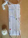
Also, when the door is closed and the transistors are off, they might not be off. The right-side transistor (reference designators - !) base is floating when the left side transistor is off, again, an opportunity for radiated noise to cause false circuit action. Add a 10K resistor from the right-side-transistor to GND.
ak
Also, 100K is a very large value for such a high gain circuit, and enables false tripping due to noise. Reduce to 10K.
Also, when the door is closed and the transistors are off, they might not be off. The right-side transistor (reference designators - !) base is floating when the left side transistor is off, again, an opportunity for radiated noise to cause false circuit action. Add a 10K resistor from the right-side-transistor to GND.
ak