Maker Pro
Maker Pro

Simple Hall sensor alarm circuit?

Alistair Ballantyne

Nov 16, 2020
33
Joined
Nov 16, 2020
Messages
33
Hi, I want to make a circuit to attach to a door.
Though it couldn't be easier with a Hall sensor and magnet - but I'm struggling and don't know why!
I'm using a Y3144 sensor.
I made the most basic circuit - see circuit 1 and the magnet does nothing.
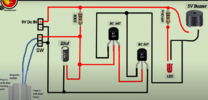
Tries a more complex circuit from an online source - Door Open Alarm Circuit. the buzzer sounds but the magnet does not control the on/off function.
Can I have damaged the sensor playing around with different circuits, is there a different sensor I should be using - or are the circuits not fit for purpose?
Would appreciate someone sanity checking this please.
Many thanks,
Alistair
 

danadak

Feb 19, 2021
780
Joined
Feb 19, 2021
Messages
780
Circuit 1 where is pic or datasheet doc you found this in ?
 

Martaine2005

May 12, 2015
4,956
Joined
May 12, 2015
Messages
4,956
All you need is a Reed switch (alarm switch), buzzer and battery.
No circuitry required.
 

Alistair Ballantyne

Nov 16, 2020
33
Joined
Nov 16, 2020
Messages
33
Circuit 1 where is pic or datasheet doc you found this in ?
Hi - Doc 1 is something I made - thought it was just the basic hall effect principle.
Buzzer sounds when magnet is not near the sensor and closes when magnet is near.
Have I got that principle wrong?
The other circuit I saw online so I have no idea how robust it is.
Thanks
 

bertus

Moderator
Nov 8, 2019
3,345
Joined
Nov 8, 2019
Messages
3,345
hello,

there is no doc or datasheet.
please post the picture.
without the picture we can give no advice.

bertus
 

bertus

Moderator
Nov 8, 2019
3,345
Joined
Nov 8, 2019
Messages
3,345
hello,

the sensor seems to be a hall effect sensor with an open collector output:
an open collector output needs a pull- up resistor to work.

bertus
 

ChosunOne

Jun 20, 2010
483
Joined
Jun 20, 2010
Messages
483
You seem to want something to sound when a door is open, and keep sounding until the door is closed, any time, day or night. In the Alarm Industry, we don't call that an "alarm", we call it "annunciation." I would say we call it "chime" except that the chime feature in all alarm panels gives one or a few (depending on the model of control panel) short beeps when the door is opened while the system is disarmed, (so no LOUD sirens or calls to police) then falls silent until the door is opened again. I suspect you might end up preferring that protocol, but I'm going to respond to what you said you wanted.

Martaine2005 is correct: For what you said you wanted, a Reed switch with magnet, buzzer, and battery is all you need, as per his diagram. I _would_ include a resistor (as he did in his diagram) to limit the current: Alarm Reed switches aren't rated for much current and alarm sensor circuits typically don't carry more than a few milliamps.
If you insist on using a Hall-effect sensor instead of a Reed switch, then it gets a bit more complicated, and will need more circuitry. There are plenty of people here to help you with that.
 

Alistair Ballantyne

Nov 16, 2020
33
Joined
Nov 16, 2020
Messages
33
hello,

there is no doc or datasheet.
please post the picture.
without the picture we can give no advice.

bertus
Hi Bertus,
Not sure why the docs not uploaded.
Screen shot of my own little hall effect circuit:
1709309757252.png
No idea why this is not working - seems idiot proof to me?
 

AnalogKid

Jun 10, 2015
2,904
Joined
Jun 10, 2015
Messages
2,904
Yes, you probably have damaged the sensor. With pin 3 connected directly to 9 V, when the sensor is tripped it attempts to put a dead short across the battery. This probably has blown its output transistor.

To correct this, break the connection between pins 1 and 3, and connect the buzzer between pins 1 and 3. The sensor's output transistor now will switch the - side of the buzzer between an open circuit and GND.

ak
 

Harald Kapp

Moderator
Moderator
Nov 17, 2011
13,752
Joined
Nov 17, 2011
Messages
13,752
1709311427052.png
You shorted the output to Vcc, then connect the buzzer between Vcc and GND.
Either the buzzer is always on when the transistor in the sensor is off,or the buzze ris always off when the transistor in the sensor is on. It all depends on the quality of your 9 V source (block battery?).
Here's how you connect the elements correctly:
1709311668186.png
 

Alistair Ballantyne

Nov 16, 2020
33
Joined
Nov 16, 2020
Messages
33
View attachment 62917
You shorted the output to Vcc, then connect the buzzer between Vcc and GND.
Either the buzzer is always on when the transistor in the sensor is off,or the buzze ris always off when the transistor in the sensor is on. It all depends on the quality of your 9 V source (block battery?).
Here's how you connect the elements correctly:
View attachment 62918
Thank you - that arrangement works!

Further confusion though.

The buzzer is on when the magnet is near the sensor but off when the magnet is removed. I thought the principle was the other way round?

  • Is this what you mean by the transistor either being on or off and how could you reverse the situation where the buzzer sounds when the magnet is removed from the sensor?
  • Does this diagram relate to your colleagues suggestion of “breaking the connection” between pins 1 and 3?
 

Harald Kapp

Moderator
Moderator
Nov 17, 2011
13,752
Joined
Nov 17, 2011
Messages
13,752
Further confusion though.
Read the datasheet (link)
1709374654137.png
When the magnet is near, the transistor is on, pulling the output to GND.
When the magnet is removed, the transistor is off.
You will need an inverter for the operation you describe. Since the hall sensor's output is open collector you will also need an additional pull-up resistor.

Does this diagram relate to your colleagues suggestion of “breaking the connection” between pins 1 and 3?
Definitely.
 

Alistair Ballantyne

Nov 16, 2020
33
Joined
Nov 16, 2020
Messages
33

Alistair Ballantyne

Nov 16, 2020
33
Joined
Nov 16, 2020
Messages
33
Or a different Hall sensor. IIRC, don't the same people make one that has an open output in the presence of a field? Not at my computer; can't search.

ak
I'll check - but I'm thinking the Reed switch option would be an easier route - as previously suggested.
I've ordered a couple of makes.
Will try this circuit which seems to make sense to me.
Is this a robust circuit in your opinion?

1709399613538.png
 

Attachments

  • 1709399491752.png
    1709399491752.png
    303.2 KB · Views: 3
Top