Maker Pro
Maker Pro

Rice cooker tripping breaker when switched on (Zojirushi NP-HCC10)

BobGrean

Apr 12, 2024
5
Joined
Apr 12, 2024
Messages
5
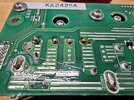
I have a induction rice cooker that trips the breaker as soon as it's plugged in. The internal 15A fuse is still intact. I disconnected the inductive loop and the unit still trips out. I have narrowed it down to the inductive power supply board pictured below. When this board is connected and nothing else is it trips out. With it disconnected it stays on.

I went through the board but didn't find anything obvious. I'm no expert though, any help or advice on finding the short circuit would be much appreciated.20240412_155025_001.jpg20240412_154858.jpg20240412_154918.jpg20240412_161505.jpg20240412_161432.jpg20240412_154846.jpg
 

Attachments

  • 20240412_145640.jpg
    20240412_145640.jpg
    439.4 KB · Views: 5
Last edited:

Bluejets

Oct 5, 2014
6,946
Joined
Oct 5, 2014
Messages
6,946
DB (first photo) shows dead short on bridge rectifier AC inputs and the negative out.
No reading shown for the positive out.
If this is the case then remove DB and test out of circuit...plenty of instructions on youtube etc. on how to test.
Note that removal needs good soldering ability and a good iron with plenty of flux and some 60/40 solder and solder wick.
Also note you cannot test the caps in circuit, ie they must be removed first, at least one leg and discharged first.
 

BobGrean

Apr 12, 2024
5
Joined
Apr 12, 2024
Messages
5
Thanks Bluejets!
Either you are a genius, or I am a idiot. In this case I would say both. It has been a couple of years since I took a circuit analysis class.

Here is a picture of the positive out.20240412_155025_001.jpg

And here is a picture of testing the bridge rectifier (DB) in circuit. I will remove it and test again out side of the circuit. I will post the results, possibly after I find a replacement.20240412_154939.jpg

(Edit)
I just removed the bridge rectifier, the results are the same as above when testing the diodes.20240412_223646.jpg
 
Last edited:

Bluejets

Oct 5, 2014
6,946
Joined
Oct 5, 2014
Messages
6,946
Ok...when testing diodes, you need to have the meter on "diode test" to bias the diode on, which it appears you have done.
Then you need to test for forward AND reverse.
Youtube will again show how to do, but it appears the bridge is kaput on the negative to AC legs.

example .............

Once you get a new device installed, best to rig up a "current limit" device to test the supply so you don't go blowing fuses all over the place.
I use a 120w flood lamp (tungsten element type, not LED or fluro or CFL) wired in series with the mains input.

That way if you still have a short somewhere, it will show the lamp full brilliance.
Obviously you are playing with mains voltages so the usual beware warning for armatures is current and cannot be over emphasised.
 

ramussons

Jun 10, 2014
466
Joined
Jun 10, 2014
Messages
466
There is a Switching Transistor (MosFet/IGBT) (mounted on a massive heat sink) that feeds the Induction Coil. That is a short. Maybe due to overheating. Check all components in its driver chain.
Use an incandescent bulb Indicator in series with the supply as advised in Post #4 to prevent additional component failures when troubleshooting.
 

BobGrean

Apr 12, 2024
5
Joined
Apr 12, 2024
Messages
5
Thanks again Bluejets, ramussons and Delta Prime.

I'm at a bit of a loss. The bridge rectifier came in the mail and I installed it with additional thermal paste on the heat sink.
1000054108.jpg

I wired it up as y'all recommended with an incandescent bulb in series. Now when I put line voltage to it the incandescent bulb is very bright! And nothing functioning. But if I remove the two wires for the induction coil and put line voltage to it, everything seems to power up fine (cooling fan turn on and the display functions) and the incandescent bulb is about half as bright.

I'm still reading 0.2 ohms on the induction coil, which is the same as I get when I touch my leads together, basically nothing.
1000054116.jpg

Any ideas on what might be wrong? It seems weird that now everything works as long as the induction coil is disconnected, and nothing works when it is connected. Nothing on the coil looks off, so I'm thinking the 0.2 ohms is probably fine and it just another component that is malfunctioning only when the coil is connected, but I do not know what would cause this.
 

Attachments

  • 1000054108.jpg
    1000054108.jpg
    468.1 KB · Views: 0

Bluejets

Oct 5, 2014
6,946
Joined
Oct 5, 2014
Messages
6,946
I wired it up as y'all recommended with an incandescent bulb in series. Now when I put line voltage to it the incandescent bulb is very bright!
That is what the lamp is supposed to do(along with saving your new bridge rectifier and possibly other components) ...If you still have an fault somewhere else in the circuit.
 

Tha fios agaibh

Aug 11, 2014
2,253
Joined
Aug 11, 2014
Messages
2,253
I suspect that IGBT has shorted.
I'd pull it out of circuit and test.

Also, the element coil may also be bad if it's only 0.2 ohms. What does you ohm meter read with test leads together?

I would expect it should read a few ohms or more.
 

ramussons

Jun 10, 2014
466
Joined
Jun 10, 2014
Messages
466
Read Post #5 again.

The best possibility is a shorted IGBT. Make sure that the cooling part is dust free before replacement. A higher current rated IGBT is better.

The bad possibility is a failed Gate drive - it is a long chain and tracking down the faulty component is not simple. You will need a scope to troubleshoot.
 

BobGrean

Apr 12, 2024
5
Joined
Apr 12, 2024
Messages
5
I suspect that IGBT has shorted.
I'd pull it out of circuit and test.

Also, the element coil may also be bad if it's only 0.2 ohms. What does you ohm meter read with test leads together?

I would expect it should read a few ohms or more.

I pulled the IGBT, and it was indeed shorted. I should have a replacement in a few weeks.​

Ramussons, I decided to go with an identical IGBT, thanks for the input though. I will also look into the gate drive if the issues persists after replacing the IGBT.​


Regarding the induction coil, the reading is the same testing the coil as touching the leads together (0.2 ohms). I was operating under the assumption that the impedance in induction coils is very low, although I would have thought there would be a small delta. How much impedance would the other guys expect out of a coil like this? Just want to make sure this low impedance is abnormal, meaning the coil is shorted somewhere.
 

Bluejets

Oct 5, 2014
6,946
Joined
Oct 5, 2014
Messages
6,946
Just want to make sure this low impedance is abnormal, meaning the coil is shorted somewhere.
You will be measuring dc resistance with a standard multimeter, not impedance.
Series lamp when used will give indication of any remaining short.
 

BobGrean

Apr 12, 2024
5
Joined
Apr 12, 2024
Messages
5
You will be measuring dc resistance with a standard multimeter, not impedance.
Series lamp when used will give indication of any remaining short.
I had to look up the difference between impedance and resistance Bluejets, I now understand that resistance is a more precise term for purely resistive elements, and can only be used in ac circuits. Thanks I will try to keep this in mind in the future. Please replace the instances of impedance with resistance in my previous post.

The question still stands, would you expect to see a measurable resistance in an inductive coil like this?
 
Last edited:
Top