Maker Pro
Maker Pro

Need help with repair

sacentre

Sep 27, 2014
29
Joined
Sep 27, 2014
Messages
29
Hi, Newbie here.

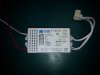
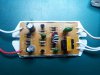
I'm hoping to get some help or advice about how to repair the ballast circuit of my bench magnifier light (here) http://i74.photobucket.com/albums/i280/sacentre/20140926_225250.jpg

It's a no-brand model from an unknown manufacturer in China and looks identical to this one http://i74.photobucket.com/albums/i280/sacentre/BenchMountedMagnifier.jpg. I don't expect the photo will help much.

The store I bought it from earlier this year doesn't sell them anymore and couldn't care less about helping me to get it repaired. I might have just bought a new one if they'd been available.

I'm afraid I'm not very good at fault finding and diagnostics but sometimes I get lucky with guesswork. On this PCB, I can see 2 burned resistors - R2 and R1 (just to the left of the upper SR 6863D). As far as I can tell, the damaged resistors appear to be colour coded red, black, black = 20 Ohms. Assuming someone is familiar with this type of circuit, does that sound right? One side of each resistor is connected to the left leg of the transistor viewed from the front.

I would guess that as well as the burned resistors, the two SR 6863D semiconductors have blown.

Can anyone tell me what the SR 6863Ds are or better still, suggest an equivalent? I've tried Googling for hours but haven't been able to find an information about them. I tried asking at my local electronics store but they didn't recognise the number.

Thanks in advance.

Trevor
 

KrisBlueNZ

Sadly passed away in 2015
Nov 28, 2011
8,393
Joined
Nov 28, 2011
Messages
8,393
Hi Trevor and welcome to Electronics Point :)

We can probably help, but we definitely need more information on this board.
  • Can you take some better photos. One from directly above and one from directly below, centred and with no rotation so we can line them up and trace out the circuit. See https://www.electronicspoint.com/resources/how-to-take-photos-of-circuit-boards.6/
  • Can you give us the markings on the following components. Either annotate them on the picture, or list them separately. The brown capacitor next to where the mains wires come in. The four green mylar capacitors. The two vertically mounted resistors whose colour bands can't be seen on the photo. The small pale blue diode near R2 (you may need to desolder and lift one end to see all the markings; be gentle - it's made of glass.)
  • Can you measure both of the resistors you removed from the board. I don't think they're the cause of the failure.
  • Can you measure (in circuit is fine) the resistor in the corner, next to the brown capacitor and the tall 10 µF/400V electrolytic. It looks like it's shrouded in a plastic cover of some kind. It's probably a fusible resistor, and if it measures more than 1 kΩ, it has probably gone open, probably due to failure of the transistors. In this case, can you remove the outer covering and read the colour bands or other markings on the component inside.
Any photos you take are probably best uploaded here. Use the "Upload a File" button at the bottom of the post edit window.

The SR6863D data sheet you uploaded on photobucket says it's a TO-126 but those ones you have there are TO-220. They could have the same, or similar, specifications though. But that page doesn't have all the important specifications. It just lists IC=3A, VCEO=400V and PD=30W and mentions high switching speed. Suitable replacements would be Fairchild FJP5027OTU: http://www.digikey.com/product-detail/en/FJP5027OTU/FJP5027OTU-ND/1054467, ON Semiconductor MJE18004: http://www.digikey.com/product-detail/en/MJE18004G/MJE18004GOS-ND/919500, STMicroelectronics BUL1102E: http://www.digikey.com/product-detail/en/BUL1102E/497-12147-ND/2827081 (all of these require an external antiparallel diode), or the STMicroelectronics BUL39D: http://www.digikey.com/product-detail/en/BUL39D/497-7203-5-ND/1037762

Edit: Can you add your location to your profile, and tell us what component supplier(s) you use.
 
Last edited:

sacentre

Sep 27, 2014
29
Joined
Sep 27, 2014
Messages
29
KrisBlueNZ

Many thanks for this. It's far more help than I have a right to expect! I'll start on it right away but it'll take me some time to take the photos and post all the info you've requested as soon as possible.

By the way I'm in Singapore.

Thanks once again.

Trevor
 
Last edited:

sacentre

Sep 27, 2014
29
Joined
Sep 27, 2014
Messages
29
KrisBlueNZ

Replies in red below.

Can you take some better photos. One from directly above and one from directly below, centred and with no rotation so we can line them up and trace out the circuit. See https://www.electronicspoint.com/resources/how-to-take-photos-of-circuit-boards.6/

I hope these are OK. The component side one isn't as sharp as I would like but it should be clear enough. I'm happy to post more from different angles if you need me to.

Can you give us the markings on the following components. Either annotate them on the picture, or list them separately. The brown capacitor next to where the mains wires come in. C1 = 104J 400v

The four green mylar capacitors. C5 = 223J, C6 = 102J, C7 = 473J, C8 = 562J

The two vertically mounted resistors whose colour bands can't be seen on the photo. R3, R4 = 1.8Ω (brown, grey, gold, gold)

The small pale blue diode near R2 (you may need to desolder and lift one end to see all the markings; be gentle - it's made of glass.) D5BT3 (or could be DSBT3)

Can you measure both of the resistors you removed from the board. I don't think they're the cause of the failure. R1, R2 These are badly burned but are both 20Ω (the red, black, black bands are still visible on one side).

Can you measure (in circuit is fine) the resistor in the corner, next to the brown capacitor and the tall 10 µF/400V electrolytic. It looks like it's shrouded in a plastic cover of some kind. It's probably a fusible resistor, and if it measures more than 1 kΩ, it has probably gone open, probably due to failure of the transistors. In this case, can you remove the outer covering and read the colour bands or other markings on the component inside.

It looks identical to a fuse (see photo) except it has solder leads like a resistor. It's in series with the 220VAC Line rail and one side of C1. The PCB location is labelled "RD" and it has "F1.5A L250v" stamped on one end cap. There are no bands or other markings. It's open circuit (no resistance reading at all on the MM).


The MJE1005 was suggested as an equivalent for the SR6863D. Would that do, do you think? I was able to get a couple of those fairly easily today.

Many thanks once again for your help.


Trevor
 

Attachments

  • Component Side.JPG
    Component Side.JPG
    95.8 KB · Views: 1,780
  • Solder Side.JPG
    Solder Side.JPG
    120.6 KB · Views: 852
  • Fuse 1A, 250v.JPG
    Fuse 1A, 250v.JPG
    110 KB · Views: 598

sacentre

Sep 27, 2014
29
Joined
Sep 27, 2014
Messages
29
KrisBlueNZ

Just to add a bit of information to the above.

1. I removed the blue diode to check the ID and the markings are printed in two lines around the body, one on top of the other as;
DB3
ST (or 5T). Sorry for the incorrect information above.

I can't tell if it's defective or not though. With my MM (Fluke 83 III) set to the diode symbol, the reading is "0" with the probes either way around. With the MM set to the Ohms scale, I get around 28MΩ one way and zero the other. Does that sound like it's shot?

2. I established that the 10uF elcap was faulty so this has been replaced.

3. R1, R2 20Ω resistors have been replaced.

Trevor
 

KrisBlueNZ

Sadly passed away in 2015
Nov 28, 2011
8,393
Joined
Nov 28, 2011
Messages
8,393
Hi Trevor and sorry for the delay.

I've drawn up the schematic of that board:

270516.001.GIF

("RD" is shown on that diagram as a fusible resistor but it seems clear that it's actually just a fuse.)

Fixing this board would involve replacing all the semiconductors, and "RD". This would only be worthwhile if you are determined to fix that board.

If you just want to get the lamp going again, you might be better off to buy a new ballast board. These are available from eBay (search for electronic ballast, and check the rated wattage) for around USD 5, which is probably a fraction of what you would spend on just the postage getting the replacement components.

If you're serious about fixing the board, here are the components you'll have to replace, with links to the pages for suitable replacements at Digi-Key:

  1. RD (1.5A slow-blow fuse) replace with http://www.digikey.com/product-detail/en/3JS 1.5-R TR/507-1647-1-ND/3516815
  2. D1~4 (bridge rectifier diodes) replace with 1N4007 http://www.digikey.com/product-detail/en/1N4007/1N4007FSCT-ND/965481
  3. D5 replace with UF4007 http://www.digikey.com/product-detail/en/UF4007/UF4007CT-ND/965732
  4. Q1,2 SR6863D replace with BUL39D http://www.digikey.com/product-detail/en/BUL39D/497-7203-5-ND/1037762
  5. D6(?) (the small blue glass device near R2) replace with DB3 diac http://www.digikey.com/product-detail/en/DB3TG/DB3TGCT-ND/2444819
From your information it's clear that the diac (item 5) has failed. The bridge rectifier diodes (item 2) have almost certainly failed; at least, they have been stressed. D5 (item 3) may possibly be OK but will have been stressed as well.

Re using MJE1005 to replace Q1,2: I can't find any information on "MJE1005" but it's unlikely to be suitable - these transistors need to have reverse-connected diodes built into them, and not many have that feature.
 

sacentre

Sep 27, 2014
29
Joined
Sep 27, 2014
Messages
29
KrisBlueNZ, no apology necessary. I'm most grateful for the trouble you've taken over this. Thank you. I shall keep the circuit on file for future reference.

I managed to replace the busted parts which were easy to match to the original specs.
R1, R2
RD
C2
DB3 diode (a "bidirectional diode" is a new one on me)

The bridge rectifier diodes all tested ok with my MM.

As for Q1, Q2 do you think it's worth trying adding a diode to each of the MJE1005s? If so, maybe you could suggest a type. I've uploaded the datasheet for the MJE1005.

I'll continue to play around with it for now but meanwhile, I see that these ballasts are easily available off eBay so I'll get a couple of spares ordered. I kinda assumed being such a simple circuit it would be easy to repair but hadn't counted on hard to find semiconductors - especially when these ballasts are being churned out in their millions.

Many thanks again.

Trevor
 

Attachments

  • MJE13005 Power Transistor.pdf
    317.5 KB · Views: 265

KrisBlueNZ

Sadly passed away in 2015
Nov 28, 2011
8,393
Joined
Nov 28, 2011
Messages
8,393
Ah. An MJ13005 is not the same as an MJ1005! One little digit makes a lot of difference :)

The MJ13005 looks suitable, but yes, you'll need to add a diode externally across each one. A high-speed diode rated for at least 400V and at least 1A continous. Something like a 1N4937: http://www.digikey.com/product-detail/en/1N4937/1N4937FSCT-ND/2053054

Did you check the diode I identified as "D5" in the schematic? Is it actually D5 on the PCB? Do you know what the markings are?

I would replace the bridge rectifier diodes even if they measure OK. The current that blew that fuse went through at least two of those diodes. It's a quick and cheap pre-emptive strike that could save trouble in the future.
 

sacentre

Sep 27, 2014
29
Joined
Sep 27, 2014
Messages
29
Ah. An MJ13005 is not the same as an MJ1005! One little digit makes a lot of difference :)
Apologies for the typo. Yes, MJ13005.
The MJ13005 looks suitable, but yes, you'll need to add a diode externally across each one. A high-speed diode rated for at least 400V and at least 1A continous. Something like a 1N4937: http://www.digikey.com/product-detail/en/1N4937/1N4937FSCT-ND/2053054
http://www.digikey.com/product-detail/en/1N4937/1N4937FSCT-ND/2053054
Noted. Thank you.
Did you check the diode I identified as "D5" in the schematic? Is it actually D5 on the PCB? Do you know what the markings are?
Sorry for not supplying this information before. It is D5 and it's marked as "FR107ZX". I've attached a datasheet. I have no idea what the "ZX" suffix means. I know if it's a "P" it means "plastic". I'm guessing the "FR" is for "fast recovery"
I would replace the bridge rectifier diodes even if they measure OK. The current that blew that fuse went through at least two of those diodes. It's a quick and cheap pre-emptive strike that could save trouble in the future.
Noted. Will do. As well as D5.

Thanks again.

Trevor


(Quoting fixed -- KrisBlueNZ)
 

Attachments

  • FR107 Diode.pdf
    51.7 KB · Views: 249
Last edited by a moderator:

KrisBlueNZ

Sadly passed away in 2015
Nov 28, 2011
8,393
Joined
Nov 28, 2011
Messages
8,393
Cool. Here's an updated schematic.

270516.002.GIF
 

A. S.

Nov 11, 2014
1
Joined
Nov 11, 2014
Messages
1
Hi,

I have the same lamp and had the same problem. I replaced the circuit with OSRAM's Quicktronic GT-ECO circuit, suitable for 10 to 24W lamps. I took out the PCB from the small plastic housing, had to file it about 1/2 mm on the shorter side for an exact fit and its performance was better than the cheap Chinese circuit.

By the way, SR6863D has SR13003K and STC13003 as exact TO220 replacements if you still need to repair the board:

http://www.sxcai.com/Products_Details.asp?id=712
http://www.bjjdwx.com/thread-135831-1-1.html

And the datasheet is here:

http://alltransistors.com/pdfview.php?doc=c13003.pdf&dire=_cdil

The only difference: TO-220 equivalents can handle just a little bit of higher power.

Almost any high Voltage and medium power NPN switching transistor will work in this circuit. In fact almost all will have more gain above 4 and function easily. The internal diode can be added externally if the transistors to be used doesn't have them.

Regards
 

sacentre

Sep 27, 2014
29
Joined
Sep 27, 2014
Messages
29
A.S
Many thanks for the reply and links.

Sadly, I can't read Chinese but the datasheet is handy and I'll file it for future reference. The info you give on the SR6863D equivalent is especially useful.

Unfortunately, I never got the original circuit working despite all the excellent help and advice I received. Almost all the components were replaced with new ones. My guess is the incorrect choice of replacement for Q1 and Q2 with MJ13005 plus added diode was the culprit.

In the end, I gave up and ordered a couple of these off-the-shelf replacement ballasts (Ballast Photo 1 and 2) which are easily available on the net. They are labelled as 22W but when I tried one on my existing lamp, they were only about 2/3 as bright as compared with an identical replacement lamp unit (I bought a complete brand new one). A look inside seems to suggest they are underrated compared with the stock unit. The 2 transistors are marked as "13003" in a TO-92 plastic package. I assumed that any 22W device would work the same but clearly, this is not correct.

Many thanks once again.

Trevor
 

Attachments

  • Ballast Photo 1.jpg
    Ballast Photo 1.jpg
    95.8 KB · Views: 776
  • Ballast Photo 2.jpg
    Ballast Photo 2.jpg
    157.5 KB · Views: 1,495
Top