Maker Pro
Maker Pro

Latching circuit problem

Steve2381

Oct 19, 2011
16
Joined
Oct 19, 2011
Messages
16
Hi all

A I am not the greatest circuit designer.... can anyone help

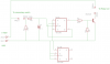
I need a circuit that wll latch on at the press of a button, and then switch off at the press of second button.
There are a few 'rules' however....

The buttons are actually reed switches. So they are only NO contacts.
The circuit cannot draw any current while off.
The whole circuit need to be as low current drawing as possible.

It will need to switch a load of around 5A. So I planned to have it operate a relay.

I found several circuits that had a single on/off button, but they monitored the button for a press and I cannot have current drain while waiting for a button press.

The simplest idea was to just have a reed relay wired up to latch on, using its own contacts. But because the 'off' button is normal open, I have no way of breaking the feed to turn it off again (hope that makes sense).

I am sure there is a simple clever way to do this...

Thanks all
 

duke37

Jan 9, 2011
5,364
Joined
Jan 9, 2011
Messages
5,364
Reed switches are available with NO and NC contacts (Maplin etc). One of each would do your job.
 

Steve2381

Oct 19, 2011
16
Joined
Oct 19, 2011
Messages
16
Checked Maplins... all their reed relays are SPST only.

I expect Farnell or someone may have some SPDT relays, but its a pain having to order just a single reed relay! Minimum orders and all that.

Just thought there would be another way - latching relays seems a bit crude.
 

Steve2381

Oct 19, 2011
16
Joined
Oct 19, 2011
Messages
16
Ah ha...
Been there! Maplin do twin coil relays.... but they are 12v coil.
I am running off 6v - hence the reed relays.

I was thinking that there would be a circuit - perhaps involving a CMOS 555 or something... that energises when you press the button and latches an output.
Then the 'off' button become available to somehow switch its state back to off.

Possibly a flip flop circuit? Isn't a 4013 a flip flop - can't remember.

Perhaps I ask too much
 
Last edited:

duke37

Jan 9, 2011
5,364
Joined
Jan 9, 2011
Messages
5,364
Look at RS 291-9704

Does it have to be a reed relay?
 

Steve2381

Oct 19, 2011
16
Joined
Oct 19, 2011
Messages
16
No - could be a normal relay. Size is an issue (its a radio controlled model) and therefore I thought a reed relay would suit due to size and current draw.

As for the 4013 idea... I just thought there might have been a way for powering the circuit with the 'on' button, and then its own output would latch the supply to that circuit in the 'on' state.
When you pressed the 'off' button, it would change its output and drop out the supply.

I think I am talking rubbish
 

(*steve*)

¡sǝpodᴉʇuɐ ǝɥʇ ɹɐǝɥd
Moderator
Jan 21, 2010
25,510
Joined
Jan 21, 2010
Messages
25,510
Steve2381, some of your requirements are contradictory, however with the extra information you've supplied I think a good answer for you is possible.

A solution using relays will fail the "consumes no power" test, however if you mean "consumes as little power as possible", a good answer *might* be:

Use a CMOS flipflop to preserve the state of the last button press -- essentially pus one button to turn on, push another to turn off. Then use the appropriate output of this flipflop to turn on a mosfet which will apply or remove power to the load.

For all practical purposes the circuit will consume no power at all, and if you select an appropriate mosfet you will easily be able to switch 5A. The only issues surround how often you switch it on and off. If you do it thousands of times per second, there will be switching issues, but I don't expect that to be the case.

You would need to have this connected permanently to the power source (as would a relay solution) but the quiescent current consumption would probably be in the order of a microamp (one millionth of an amp)
 

Steve2381

Oct 19, 2011
16
Joined
Oct 19, 2011
Messages
16
OK.
The reason for keeping the drain to zero (if I could have), is because its controlling the receiver in a model submarine.
The battery pack and receiver are in a watertight tube (with a small vent while charging the batteries). Switching the sub on and off was to be accomplished by using reed switches and a magnet - through the side of the plastic watertight tube.
Therefore, if I don't use the model for a few weeks, the system would slowly drain the battery pack.
I suppose that doesn't matter. I nearly always recharge before taking it out anyway.
 

(*steve*)

¡sǝpodᴉʇuɐ ǝɥʇ ɹɐǝɥd
Moderator
Jan 21, 2010
25,510
Joined
Jan 21, 2010
Messages
25,510
A CMOS circuit (correctly implemented) won't have any noticeable current draw. It will almost certainly be below the self-discharge current.
 

Steve2381

Oct 19, 2011
16
Joined
Oct 19, 2011
Messages
16
I found this circuit - should do the trick?
Am I right in thinking a CD4013 is the CMOS version?
 

Attachments

  • latch.png
    latch.png
    61 KB · Views: 333

(*steve*)

¡sǝpodᴉʇuɐ ǝɥʇ ɹɐǝɥd
Moderator
Jan 21, 2010
25,510
Joined
Jan 21, 2010
Messages
25,510
That looks OK. Press once for on, again for off. That doesn't match your original requirement, but may be simpler in some respects.

The 4000 series CMOS can operate from 3 to 15 volts, so the exact 5V rail is not important.

Note that the circuit diagram shows unused inputs tied to ground (good) but doesn't show the power supply pins of the 4013, so beware of that.

If you're going for lightness and low power drain, it might be useful to tell us what the load is that your turning on/off (current & voltage) because you may be able to use a mosfet to switch the load.

The other consideration is that the power to the 4013 may need to be decoupled from your main power supply, especially if there are motors operating from it (which I assume to be the case). If you're not using a relay, this is very simple to do as the entire circuit will use almost no power at all.

If you do use a relay, you will require a reverse biased diode across it to protect your transistor. Depending on the load you're switching this may also be required (it's safer).
 

Steve2381

Oct 19, 2011
16
Joined
Oct 19, 2011
Messages
16
I know this is a different idea from the original (one button now instead of two), but that actually makes life easier.
The load is going to be receiver, 4x servos and an electronic speed controller. The motors run off a different battery.
5A should cover that I think. I was thinking of a TIP122 or TIP127 (can never remember which one is NPN - PNP).
I realise the supply pins are missing to the 4013

Thanks
Steve
 

(*steve*)

¡sǝpodᴉʇuɐ ǝɥʇ ɹɐǝɥd
Moderator
Jan 21, 2010
25,510
Joined
Jan 21, 2010
Messages
25,510
The problem with using a bipolar junction transistor is the voltage drop across it (even worse with a Darlington). I recommend a power mosfet because these can have very low on resistances (measured in miliohms) so the voltage drop, and hence wasted power) is much lower. In addition it required almost zero current to turn them on and off, so as long as you're not concerned to a great deal with switching speed, they can often be driven directly from the output of the CMOS gate.
 

gorgon

Jun 6, 2011
603
Joined
Jun 6, 2011
Messages
603
Why not use a P-channel MOSFET to switch the power ON with self hold, and another transistor to turn it OFF? I'll make a diagram later this weekend when home.

TOK ;)
 

Steve2381

Oct 19, 2011
16
Joined
Oct 19, 2011
Messages
16
That will be me wading into unknown territory then..... P-channel who what?
Time to google
 

gorgon

Jun 6, 2011
603
Joined
Jun 6, 2011
Messages
603
The weekend turned out to be more than full, and no time to draw anything. I haven't forgot, yet :)

TOK ;)
 

KrisBlueNZ

Sadly passed away in 2015
Nov 28, 2011
8,393
Joined
Nov 28, 2011
Messages
8,393
Excellent advice throughout this thread, *steve*! I can see why you are a "super moderator" :)
 

(*steve*)

¡sǝpodᴉʇuɐ ǝɥʇ ɹɐǝɥd
Moderator
Jan 21, 2010
25,510
Joined
Jan 21, 2010
Messages
25,510
*steve*! I can see why you are a "super moderator" :)

It's because I talk a lot, right? :D

Here is a circuit showing how to use a P channel mosfet to switch power to something (in this case it's a 12V application, but there's nothing special about that).

screen_shot_2011_05_29_at_200256.png


If the voltage you were switching was higher than the voltage operating the CMOS flip-flop then you would use a circuit almost exactly like this.

In your case the CMOS power supply is the same as the supply to the rest of the device, so you can connect the logic output directly to the mosfet gate pin and remove the other resistors and transistor.

With the transistor in the circuit a high level input is required to turn on the mosfet. Without the transistor (which inverts the signal) a low is required to turn on the mosfet.

A logic level mosfet would be required.

You also need to protect your CMOS device from noise on the power rails caused by motors etc. The best way to do this in this case is to place a capacitor (0.1uF) as close as possible to the supply pins of the IC as possible. If noise is still a problem, you could add another larger capacitor, and/or place a low value resistor (say, 100R) in series with the power to the CMOS IC.
 
Top