Maker Pro
Maker Pro

How to troubleshoot single dim bulb/socket on Delco radio pcb?

Sergeant_Dreizehn

Jan 16, 2024
9
Joined
Jan 16, 2024
Messages
9
Hello,
I've been repairing a bunch of dead bulbs and things on my mother's 04' GMC Yukon, in the radio and the instrument cluster. Most of the repair went fine, but there is one 3mm radio bulb socket causing strange issues.

When removed from the circuit board, the bulb works fine. However, once soldered in, the bulb is really dim, even if I apply the current directly to its leads. I've tried two different bulbs and re-soldering (admittedly I'm still learning soldering), but the result is the same. They are brand new 12v incadescent bulbs, by the way.

I think the traces on the board are ok, but I don't know for sure. There's definitely an issue with power getting to the bulb, but my whole experience in PCB repair amounts to swapping out a few parts and resoldering a few pins, so I'm not sure what to do next.
Does anyone have any suggestions on what it could be or what I could try? Or if not, perhaps another place I could ask? Any assistance would be much appreciated.
Thank you.

Because of the size limit on images, here are links to them on my Google Drive:
-Front with bulbs illuminated
-Back of PCB with soldered pins
-Close up of bulb pins
-Radio face for reference

P.S. I have no idea what the clear goop is on all the solder points. If it's flux, it must be petrified, as it's hard as a rock, and I'm afraid of damaging the board if I try to clean it up any more.
 

H2814D

Nov 4, 2017
215
Joined
Nov 4, 2017
Messages
215
Have you tried the problem bulb in another socket that works correctly? Does the problem move after you do that? That will tell you if the bulb(s) is/are good for sure. I see you have tried more than one bulb there, but still. Are you able to take a dc voltage reading from the suspect socket pins without shorting anything out? How does it compare with the rest of them? Realizing you mentioned it is an incandescent bulb, but have you tried switching polarity? It may or may not make a difference with those bulbs. All of those illumination lights should be tied into the same circuit. When the head/parking lights are on, the radio illumination lights should be on.

There is a possibility you may have damaged the traces during soldering. If all else fails, you should be able to jumper wires from another nearby bulb solder point over to the problem bulb circuit. Before you do that, and to be sure the circuit is connected, check the continuity from a good working bulb socket to your suspect socket, at least at a point very close to the suspect bulb solder point. You may have to scrape off a bit of the trace insulation near the solder pins to do that. There should be continuity. If so, they are on the same circuit. If not, they may not be on the same circuit and in that case you may want to find out for sure before jumpering anything.

If you need to connect the suspect bulb circuit to a good working one, you can always jumper wires from both pin connections of a good socket to the suspect socket to fix it. That is if the traces have gone bad for some reason, but because you have some illumination there, I would doubt that is the problem.

The "clear goop" on the pins is waterproofing material.

Let us know what happens please.
 

Sergeant_Dreizehn

Jan 16, 2024
9
Joined
Jan 16, 2024
Messages
9
Thank you for your reply!
I have not tried the bulbs in a different socket yet, mostly because they both illuminated fine off of the board and read fine on the multimeter. I haven't tried flipping the bulbs yet, as I just assumed polarity wouldn't matter on incandescent bulbs. I'll try both tonight, once I've gotten some better solder wick. (what I've got came with a kit, and literally falls apart as I try to use it...-_- )

I did check continuity between all the bulb sockets, and all of them, even the dim one, gave the same reading and seem to be on the same circuit. I'll try again with the empty socket tomorrow to see if anything changes.
Should I still scrape some of the insulation away and check the trace directly? Or does the wonky bulb/socket having continuity make that unnecessary?

Also checked the voltage, and the pins for all the bulbs on the board read about the same. Of course, it's entirely possible that I've done one test or another incorrectly, so I'll probably re-check it all again regardless.

Thank you for the jumper wire suggestion. If this mystery keeps up much longer, I'll definitely try that. Is there a guideline for what gauge wire to use? I assume it would need to be at least as big as the PCB connector's wires, but I'd rather not risk going too small and have it go up in flames after I've reinstalled it.

I also appreciate the ID on the waterproofing material. I'd never seen that on a board before!
Again, thank you very much for your invaluable assistance. Hopefully I'll get some clearer results soon.
 

Bluejets

Oct 5, 2014
6,958
Joined
Oct 5, 2014
Messages
6,958
Does anyone have any suggestions on what it could be or what I could try?
Check new bulb specs against old bulb specs. i.e. voltage and wattage
Check voltage at the pins on PCB see if the same voltage as your bulb ( I kind of doubt it)
What are the "bulbs" by the way.......any pic of the old one by any chance?.......seems strange to have a 2004 auto using bulbs...one would expect to see LED's.
 

H2814D

Nov 4, 2017
215
Joined
Nov 4, 2017
Messages
215
Should I still scrape some of the insulation away and check the trace directly? Or does the wonky bulb/socket having continuity make that unnecessary?
The reason I wanted you to do that was to make sure the continuity between the bulb pins between the good bulb socket and the suspect bulb socket was actually there. And to make sure they were on the same circuit. There should be a very low ohm reading between the positive pin on an adjacent bulb to the positive pin on the suspect bulb, if they are on the same circuit. If ALL of the bulbs are on the same circuit, you should have continuity between any of the positive pins and any other positive pin. Same with the negative pins.

But if you don't have continuity at the pin, you may have to scrape off a very small bit of the insulating material. The term for that material is "solder mask." It is the thin green insulating coating over the trace. If you do the scraping right next to the pin on the suspect bulb, you will know your answer as to whether the trace and the circuit is intact from the good bulb to the suspect bulb. Hope that makes sense. There should be no reason for the trace to have failed though, unless there was a soldering issue. I don't see anything that would visually indicate failure. I suspect the bulbs being used, or a possible polarity issue, but if the bulbs are LEDs, I wouldn't even expect them to even glow dim in that low voltage socket.

One other thing for you to try. Check the ohm reading on the dim bulb and compare it to another one that burns brighter. They should all be the same, out of the circuit. If the dim one is higher, that may be the issue.

Is there a guideline for what gauge wire to use?
The traces are small. You will not need a very thick wire gauge. A 22 or 24 gauge, insulated, is enough. Too thin and it will be hard to solder.
 
Last edited:

H2814D

Nov 4, 2017
215
Joined
Nov 4, 2017
Messages
215
What are the "bulbs" by the way.......any pic of the old one by any chance?.......seems strange to have a 2004 auto using bulbs...one would expect to see LED's.
They sell bulb replacement packs for those radios. You can even get them in different colors. Some of the replacements ARE LED's, but many of the 2004 model years still used incandescent bulbs in radio illumination displays. I suspect the OP has probably purchased a recommended replacement bulb pack.
 

H2814D

Nov 4, 2017
215
Joined
Nov 4, 2017
Messages
215
Here is one other thing I have noticed on your photo with the bulbs illuminated. If you look at the upper right most bulb and then go across to the left, those bulbs look relatively brighter than the ones on the bottom row. The second row looks brighter too. The third row, to me from the pics anyway, appear to get more dim from right to left. The one next to the dim bulb is certainly dimmer than the one to its right (in the pic). That leads me to believe there may be something else causing the issue. For now, don't remove or desolder any of the bulbs and don't bother with any other tests or scraping of the traces. Leave everything alone.

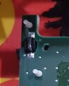
Up in the upper right corner of the picture with the bulbs illuminated is a dark cylindrical appearing component behind the green five wire plug. What is that?

Another question. You mentioned you were replacing other burnt out bulbs in the car. It sounds as if you were replacing more than just bulbs in this radio unit. Is that the case, or were there burnt out bulbs in this radio too? Which one(s) were burnt out in the radio, if you remember?

Let us know, please.
 

Sergeant_Dreizehn

Jan 16, 2024
9
Joined
Jan 16, 2024
Messages
9
H2814D,
Thanks again for replying. Great catch on the bulbs' varying brightness; I had to sit and stare at the picture for a minute to notice. As suggested, I didn't remove or resolder anything. I did re-check continuity, and all the bulbs are on the same circuit, and have a very low ohm reading.

I'm not sure if this is what you meant, but if it is, the dark cylindrical object in the picture is just tape wrapped around the plug's wires. Here's a picture from a different angle: Radio upper right

Please let me know if that's not what you were talking about.

Regarding what I was doing, the Yukon had burned out bulbs in the instrument cluster and radio, and two malfunctioning stepper motors. There were no issues replacing the bulbs and motors in the cluster. Because I had to take the radio apart anyway, I decided to replace all the bulbs except the red LED on the post. The radio uses three 5mm bulbs and seven 3mm bulbs, so I used leftover 5mm bulbs from the cluster kit and bought a pack of 3mm bulbs separate. This is them if you're interested: CEC Industries 7219 Wire Terminal (10-Pack)

Here is a picture of the board without the white rubber skin and with the location of the dead bulbs circled:
Radio board w/o skin
I can't remember for certain if the bulb on the far right was dead or not.
Please let me know if there's any other information you need, and thank you again for your assistance.
 

Sergeant_Dreizehn

Jan 16, 2024
9
Joined
Jan 16, 2024
Messages
9
Check new bulb specs against old bulb specs. i.e. voltage and wattage
Check voltage at the pins on PCB see if the same voltage as your bulb ( I kind of doubt it)
What are the "bulbs" by the way.......any pic of the old one by any chance?.......seems strange to have a 2004 auto using bulbs...one would expect to see LED's.
Hello,
The new bulbs look exactly the same as the old ones and have the same voltage. Unfortunately, I don't have the old 3mm ones anymore (or at least I can't find them at the moment...) to be able to compare wattage. The bulbs are 3mm and 5mm "grain of wheat" incandescent bulbs, 12v. The troublesome socket is for a 3mm. I don't have a picture of an old one unfortunately, but here is a new one: 3mm bulb
Yeah, it would have been nice if the Yukon had LEDs, but I think GMC and Chevrolet kept using incandescent bulbs in many vehicles until 2005 or so. What really floors me is that they used nice plug-in style bulbs in the dash for a few years, then changed back to soldering them right to the board sometime prior to 02'. Not fun! I'm just glad my Tacoma is much easier to work on.
Thank you for the suggestions!
 

kellys_eye

Jun 25, 2010
6,514
Joined
Jun 25, 2010
Messages
6,514
Please stop using Google for your pictures. This site accepts them directly and should be used - even if you have to resize them.
 

kellys_eye

Jun 25, 2010
6,514
Joined
Jun 25, 2010
Messages
6,514
The "clear goop" on the pins is waterproofing material
It's proper name is 'conformal coating' - not necessarily for waterproofing but stops all sort of issues from occurring, mainly corrosion.
 

H2814D

Nov 4, 2017
215
Joined
Nov 4, 2017
Messages
215
OK. Thanks. The reason I didn't want you to do anything else is because I now think you have a current supply problem to the bulbs and I suspect that dim bulb may be the last one in the circuit. The ones before it are absorbing enough current to limit that last one in the circuit from glowing as intended. It looks and sounds like they are installed in parallel, based on your continuity checks, so if one goes out, the rest stay lit. And I don't mean to be insulting, but I need to know that you know the difference between a continuity check and an voltage check? You will be doing continuity checks without 12vdc power supplied to the board.

I see the bulbs you installed are rated at 12 vdc, so the next test should be safe to conduct. That board likely does not have a power supply built into it, so the current to supply those bulbs has to be coming from the molex plugs that are attached to another part of that radio system. You should be able to locate which wires those are, by doing a continuity check from one of the pins on the first bulb in the circuit, which is probably the one in the upper right, in your supplied photo with the lamps on, to a wire in the plug (one of the three that are on that board) that gives you an electrical path (continuity). You will need to find both the positive and negative wire routes to those bulb pins from the molex connectors. The negative pin may also be grounded to that board somewhere, and is quite possibly the larger traces that make up the majority of what you see on that board. It may not be, so you have to be sure.

Once you have found the positive and negative supply wires from the molex connectors to those bulbs, take a 9 volt battery and run wires from the positive and negative sides of the battery to the positive and negative bulb pin wires in the molex connector. Be careful not to short anything out, and also be sure of the polarity before doing this. You can do it at the bulb pins, but you have to make sure you find the first one in the circuit, if there is only one path. The 9 volt battery should be enough to light up all of those bulbs. If all of them glow at about the same brightness, then the current supply issue is coming from somewhere before the molex connector and we will have to troubleshoot that part next. I have a feeling you will have all of the lights glowing brightly once you do this test though.

Once again, be careful not to short anything out, and make sure you have the correct polarity being attached to either the pins or the molex plug wires and the battery before doing the test.

Let us know what happens.
 

Sergeant_Dreizehn

Jan 16, 2024
9
Joined
Jan 16, 2024
Messages
9
Hello,

Just a quick post for now. Don’t worry, you’re not being insulting at all. I freely admit my wire/electricity etc knowledge is scant, as I only know what I’ve needed to learn to fix things. I learn best by doing. The continuity check is actually the one test I’m confident with. However, I did research using it on circuits just in case it was different than performing it on wires and bulbs. I did have to research the voltage check, as it’s been a long time since I’ve done one.

Hooking up a 9v battery is actually how I got the bulbs to light up in the original photo, except I attached alligator clips to the pads shown in the picture below. The video I watched to learn how to change the bulbs said to attach there to test all the bulbs at once, so that’s why I did that.

radio_bulb_test_pads.jpg

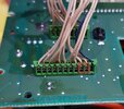
I was able to locate two pins in the connector that had continuity with all of the bulbs, but I couldn’t determine which wire was positive/negative, or which bulb was first in line. The picture below shows the pins and connector.
radio_molex.jpg

Hopefully I’ll post again later after doing some more research and another voltage test originating from the wires.

Thank you again for being so patient and willing to help a novice like me!
 

Delta Prime

Jul 29, 2020
2,007
Joined
Jul 29, 2020
Messages
2,007
Is your vehicle a 2004 GMC Yukon Denali?
And is that a Bose radio inside of it?
Any information printed on the radio itself?
I would like to try to find a schematic for it. :)
 

kellys_eye

Jun 25, 2010
6,514
Joined
Jun 25, 2010
Messages
6,514
Hooking up a 9v battery is actually how I got the bulbs to light up in the original photo, except I attached alligator clips to the pads shown in the picture below.
Bad idea. The 9V could have damaged circuitry on the board - shorted a diode, blown a transistor etc. Without a schematic we'll never be able to determine what it is you did.
 

H2814D

Nov 4, 2017
215
Joined
Nov 4, 2017
Messages
215
Have you tried putting the radio all the way back together and back into the vehicle yet?
 

Sergeant_Dreizehn

Jan 16, 2024
9
Joined
Jan 16, 2024
Messages
9
Is your vehicle a 2004 GMC Yukon Denali?
And is that a Bose radio inside of it?
Any information printed on the radio itself?
I would like to try to find a schematic for it. :)
The vehicle is a '04 Yukon SLT, but not a Denali. The original speakers are Bose, but the radio itself is made by 'Delphi Delco Electronics,' with no Bose branding anywhere.

The part number for the whole radio unit is: 15138489
The circuit board in question has a bar code sticker that reads: KB UL DOM DE-175 and C91437070197575.
Also, printed on the bottom edge of the board itself is 09391432E.
The only other numbers I found were part numbers for the CD and cassette units.

Thank you very much for your help! :)
 

Sergeant_Dreizehn

Jan 16, 2024
9
Joined
Jan 16, 2024
Messages
9
Have you tried putting the radio all the way back together and back into the vehicle yet?
Yes I did, twice. That's actually how I discovered the problem. I didn't do anything with the 9v battery until well after swapping bulbs, resoldering, etc., and making no headway.
I think I'm probably going to try running jumper wires from another bulb to see if it makes a difference. I just need to get down to the store to get the right kind of wire.
 

kellys_eye

Jun 25, 2010
6,514
Joined
Jun 25, 2010
Messages
6,514
If the radio still works then just hardwire another lamp into the circuit, taking the supply from 'wherever' on wire tails from the new lamp - or hot glue the new one into place.
 

H2814D

Nov 4, 2017
215
Joined
Nov 4, 2017
Messages
215
Yes I did, twice. That's actually how I discovered the problem. I didn't do anything with the 9v battery until well after swapping bulbs, resoldering, etc., and making no headway.
I think I'm probably going to try running jumper wires from another bulb to see if it makes a difference. I just need to get down to the store to get the right kind of wire.
Ok. My initial thoughts were that the 9 volt battery may not have been strong enough to power the lights fully, based on the age or a possible used and therefore weaker battery. As if you may have taken it out of something else for this, if that makes sense. You can get a 9 volt voltage reading off of a battery and still not have an adequate current flow from it to work the circuit properly. This is very common with watch style batteries too. That was why I asked if you had tried it in the vehicle.

So the same problem exists both in and out of the vehicle. That leads me to believe the issue is in the lamps being used. Do you have any more new and unused lamps left? There is a possibility the weaker glowing lamps you used may have been rated at a lower wattage or had higher ohm readings for the lamp filaments, even though they look the same. I did notice you mentioned there were some larger (5mm) bulbs and some smaller (3mm) bulbs you replaced, but you also mentioned that the suspect bulb had the same brightness as the others (small ones) when out of circuit.

Try this next. Do a resistance (ohm) reading on each bulb while they are in the circuit. Which means putting the positive and negative multi-meter probes on each pin of each bulb, and tell us what you come up with. This may or may not work while the bulbs are soldered in circuit, but at least try it, you will get something. And I am only talking about testing the smaller, same size bulbs. The larger ones will obviously have different values. See if the suspect bulb gives you a substantially higher ohm reading, which is what I expect to see, if it is the bulb. If the same voltage/amperage is supplied to all of the bulb pins in the circuit, and the rest glow brightly, about the only other thing it could be to cause this problem would be a higher ohm rating or lower wattage on the bulb that is dim. I really doubt the traces are the problem, but still possible. If all of the smaller bulbs have the same reading, your next step should be the jumper wires.
 
Top