Maker Pro
Maker Pro

Help with two wires please

Martziniuk

Jan 23, 2022
8
Joined
Jan 23, 2022
Messages
8
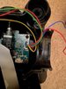
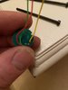
So I managed to pull two wires out of a night vision push button on/off with three stage light IR dimmer.
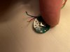
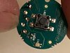
I know the blue is neutral but which hole does it belong and which hole does the red wire belong.

Thanks for any help, it’s very frustrating and I don’t want to guess.

1234.jpg
 
Last edited by a moderator:

Martziniuk

Jan 23, 2022
8
Joined
Jan 23, 2022
Messages
8
I can’t seem to post more pics but from the right the wires are yellow, blank, blank, green, red. where the blanks are either blue or red
 

Martziniuk

Jan 23, 2022
8
Joined
Jan 23, 2022
Messages
8
hi ya and welcome :)

without further info ... all anyone here would be doing is guessing
Thank you.
I’ve asked the manufacturer for clarification on where the wires go, can’t imagine they’ll be that forthcoming but I’ll go from there.
 

Martaine2005

May 12, 2015
4,955
Joined
May 12, 2015
Messages
4,955
Try posting another picture keeping it below 300Kb. But vey clear and focused. Other side of board might be helpful.
I take it that the blue and red go to batteries?

Martin
 

Martziniuk

Jan 23, 2022
8
Joined
Jan 23, 2022
Messages
8
The two wires that have pulled out are pins 1 and 5 in the plug.
 

Attachments

  • DAA67188-9CF5-41C9-A09E-B99C0229F686.jpeg
    DAA67188-9CF5-41C9-A09E-B99C0229F686.jpeg
    250.1 KB · Views: 8
  • 7AF39FB7-A336-4EF9-9332-81A923996206.jpeg
    7AF39FB7-A336-4EF9-9332-81A923996206.jpeg
    113.7 KB · Views: 8
  • 12AA4FF6-62E8-4D4A-A2DB-B42AE07CB1EF.jpeg
    12AA4FF6-62E8-4D4A-A2DB-B42AE07CB1EF.jpeg
    195.9 KB · Views: 8

Externet

Aug 24, 2009
892
Joined
Aug 24, 2009
Messages
892
On your image with arrows marked; the left arrow supplies one side of voltage to both LED indicators. The right arrow connects to the push switch.
If unable to discern beyond, try to sketch a schematic for the traces corresponding to wires 1 and 5 on the plug. Perhaps one is connected to common ground or battery (-) The other may be (+) to the switch. Check very magnified if the anodes or the cathodes of the dual LED are the joined. They have a tiny identifier on a corner.

If the cathodes are the joined terminals on the LEDs, tells the battery (-) connects there, whatever the wire color.
Mark now! the other wires colors location before they break-off too.
 

Martziniuk

Jan 23, 2022
8
Joined
Jan 23, 2022
Messages
8
On your image with arrows marked; the left arrow supplies one side of voltage to both LED indicators. The right arrow connects to the push switch.
If unable to discern beyond, try to sketch a schematic for the traces corresponding to wires 1 and 5 on the plug. Perhaps one is connected to common ground or battery (-) The other may be (+) to the switch. Check very magnified if the anodes or the cathodes of the dual LED are the joined. They have a tiny identifier on a corner.

If the cathodes are the joined terminals on the LEDs, tells the battery (-) connects there, whatever the wire color.
Mark now! the other wires colors location before they break-off too.
The blue is a negative as it says on the main board connector in the picture. I will have a very close look later to see what’s written in the cathode. Thank you so much for your help
 

Martziniuk

Jan 23, 2022
8
Joined
Jan 23, 2022
Messages
8
I’m afraid I failed to read any numbers, this is as close as I could get, even with a magnifying glass.
 

Attachments

  • 75E755F2-EE9E-4B24-AADB-F00D78700B19.jpeg
    75E755F2-EE9E-4B24-AADB-F00D78700B19.jpeg
    210.2 KB · Views: 5

Martziniuk

Jan 23, 2022
8
Joined
Jan 23, 2022
Messages
8
Update.
The manufacturers were useless and wouldn’t release any info on which way the wires went. I decided that the right side of the board was a red positive which went through the led so decided it needed the neutral on the exiting side. It’s all working again now,
Big thanks to Externet for his advise.
 
Top