Maker Pro
Maker Pro

Help repairing fish tank led light

Allwaystryingtofix

Nov 24, 2016
15
Joined
Nov 24, 2016
Messages
15
Hello everyone.
I'm looking for some help to repair a fish tank led light.
It had got wet as the tank was over filled and now only some of the led's work.
As a project I'd like to test it and resolder any failed smd led's etc or the little black resistors I'm guessing?? .
I'm sure with some guidance and help I can fix it. A new one is £50 and I expect parts from rs would only be a few pounds.

If I can post a few close up images can you guys help if I get my multi meter!!???

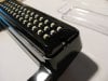
It looks like this. I've had apart before. not much inside it on the back of the circuit.
 

Attachments

  • IMG_8846_s.jpg
    IMG_8846_s.jpg
    151.9 KB · Views: 86

Tha fios agaibh

Aug 11, 2014
2,253
Joined
Aug 11, 2014
Messages
2,253
I suspect your biggest obstacle will be identifying and sourcing similar replacement leds. If you know the led part number that'd be a big help.
 

Allwaystryingtofix

Nov 24, 2016
15
Joined
Nov 24, 2016
Messages
15
OK. Here is a closer image of the board. If I switch it on,6 led's illuminate near the wire end.
Most of the other led's will illuminate in different patterns or so if I gently touch a small driver on random bulb terminals but only if I touch the metal blade of the driver with my finger as well ??

The long black resistor bank on the side, these are labeled 1500 on one side and look a bit roughed up from shorting in water???.

There are two on the opposite side of these and are labeled r270.

Also, when I was drying it, one was knocked off next to the black wire.Not sure what it was, perhaps an r270??

The black component is labeled M7 by the white wire.

Any help gratefully appreciated to test things and get it going. !!!
 

Attachments

  • DSC_0623.JPG
    DSC_0623.JPG
    274.7 KB · Views: 74
  • 1480108420618846302434.jpg
    1480108420618846302434.jpg
    355.4 KB · Views: 87

Tha fios agaibh

Aug 11, 2014
2,253
Joined
Aug 11, 2014
Messages
2,253
Looks to me like the array is wired with a resistor limiting current on each bank of 3 leds which are in series. It could be a bad resistor or diode but I'd guess the leds got fried from rogue currents.
If any one led is burned out it will keep the rest from lighting in that string. You could use a battery to find the bad leds needing replacement or a continuity tester or sometimes a dvm in continuity mode will work because the voltage it puts out. They should operate around 2.5 or 3 volts. check for proper polarity.
 

Allwaystryingtofix

Nov 24, 2016
15
Joined
Nov 24, 2016
Messages
15
I think I need to replace 20 led's.
I can do that. But how do I test the black resistors?
And one is missing at R15 in the corner. What is it likely to be?
 

Tha fios agaibh

Aug 11, 2014
2,253
Joined
Aug 11, 2014
Messages
2,253
Their may be leds out because of the missing resistor. Flip the board over and follow the traces to see how the circuit is wired, then draw a circuit diagram so the resistor can be calculated provided the voltages and led specs are know.
You can test resistors with your meter on ohms scale.
 

Allwaystryingtofix

Nov 24, 2016
15
Joined
Nov 24, 2016
Messages
15
It's blank on back. the circuit is on the top under a black film.

How do I test the resistors? what should the dvm setting be on?
What am I looking for on the display?
 

Tha fios agaibh

Aug 11, 2014
2,253
Joined
Aug 11, 2014
Messages
2,253
Resistors that read R1500 are 150Ω. R270 are 27 ohms.
Put your meter on ohms scale if its an autoranging meter, or 200 ohms range if manual. See what you get.
Also see what voltages you get at the 3 wires.
Always start on highest voltage range, then switch to lower range if needed.
 

Tha fios agaibh

Aug 11, 2014
2,253
Joined
Aug 11, 2014
Messages
2,253
I looks to me it might be a 12v circuit; where each of the led has a forward voltage of 3v (times 3) and the 150 ohm resistor drops the other 3 volts. 3/150=.02 amp thrugh each group of 3.
You'll need to do some detective work to find the missing resistor value. Does the light have low and high settings? If so, do you remember where and how many leds turned on when on low setting? Where does the three wires originate?
I would try and draw a picture of the tracer paterns so we can figure out the circuit.
I can see part of it in the photos but its not clear, primary where R15, R16, R17 tie in.
 

Allwaystryingtofix

Nov 24, 2016
15
Joined
Nov 24, 2016
Messages
15
Yes, it's 12v input 400ma. There is no low /high. Just a three way switch. One side illuminates the 3 single night glow blue leds, the other side of the toggle illuminates the rest of the white leds.
I have feeling r14 15 16 17 have something to do with the blue leds???
 

Attachments

  • _20161201_162104.JPG
    _20161201_162104.JPG
    289.2 KB · Views: 72

Tha fios agaibh

Aug 11, 2014
2,253
Joined
Aug 11, 2014
Messages
2,253
I would try and draw a picture of the tracer paterns so we can figure out the circuit.
Have you done this? Again, if the circuit is known the resistor can easily be calculated.

For instance I can see R2, L4,L5,L6 are all on one string and then connect to the common tracer on bottom of board. If this is sketched out, we will know how its wired. (3 leds in series with a R150 current limiting resistor.
 

Allwaystryingtofix

Nov 24, 2016
15
Joined
Nov 24, 2016
Messages
15
No. I can't really see what goes where. its under a thick black coating. probably easy to the trained eye.

I could guess the missing resistor. either a 1500 or an r270??

Or alternatively find it in the carpet pile here!!!
 

Tha fios agaibh

Aug 11, 2014
2,253
Joined
Aug 11, 2014
Messages
2,253
2016-12-02 17.42.23.jpg Guessing is not wise. Do you really want to go through all the trouble of replacing parts only to have it fry?
I can see a repeated tracer pattern, I just can't see the entire circuit from your pics.
 

cjdelphi

Oct 26, 2011
1,166
Joined
Oct 26, 2011
Messages
1,166
Ebay has bags of these, 100 for a couple of bucks...

I don't suspect the LEDs at fault but the copper tracks under the leds, they could be rusted...

Desolder (keep note on the polarity of each led, a little cut out corner of each led, they match going back on) look for rust or eaten tracks
 

cjdelphi

Oct 26, 2011
1,166
Joined
Oct 26, 2011
Messages
1,166
Infact better still..

Get a resistor and a 3-5v power supply and individually test each led, i still bet one of the tracks has just rusted (where each led leg is soldered), rinse in isopropyl is another option
 

Allwaystryingtofix

Nov 24, 2016
15
Joined
Nov 24, 2016
Messages
15
Infact better still..

Get a resistor and a 3-5v power supply and individually test each led, i still bet one of the tracks has just rusted (where each led leg is soldered), rinse in isopropyl is another option


So, I can either solder on a missing 150ohm resistors or an r270.
Which one would be safer / better to try first.
I don't know what they do but, I mean if I was going to try a fuse in a plug I would try a lower rated one first. see what I mean...
 

cjdelphi

Oct 26, 2011
1,166
Joined
Oct 26, 2011
Messages
1,166
I'm talking about testing them without lifting them...

But if there is a short nothing will light up, a 500 ohm resistor/5v will do
 

Tha fios agaibh

Aug 11, 2014
2,253
Joined
Aug 11, 2014
Messages
2,253
Yes but one is missing . Is it safer to try the fixed circuit with a 150ohm or an r270 resistor
As I said, it's not wise to guess what a component might be. It's like asking the doctor; Should I take vitamin A, or C to cure my stomach ache?

If you are insistent on proceeding with your wild guess, go with a higher value resistor.
 

Allwaystryingtofix

Nov 24, 2016
15
Joined
Nov 24, 2016
Messages
15
I decided to give up on the little board. I think water got onto everything. I couldn't see clearly where to solder the components as the board was coated in black paint or something as well.

I bought one of these and it works great.

http://www.ebay.co.uk/itm/322244849126

I want to add another to make it a little brighter and was wondering do I need to wire them in series or parallel?


Can I just solder both positive and negative cables together then join at the switch.??
 
Top