Maker Pro
Maker Pro

Fancy 12V car battery level indicator

garynobles

Jul 4, 2013
10
Joined
Jul 4, 2013
Messages
10
Hi, I have been trying to design a circuit to monitor my 12V leisure car battery, I'm thinking this should be fairly simple, but its been years since I did any real electronics.

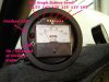
So the basic idea: Use the circular bargraph to indicate the level of the battery when a momentary push button is pressed
the circular LED bar graph: https://www.sparkfun.com/products/11492

So the range of the battery would be something like 10.5V to 13.5V, there are 32 LEDs in pairs, so essentially 16.

1. So if we take the first LED pair, this should illuminate when less than 10.5V, so that should be easy, as long as there is some life in the battery it should illuminate

2. The next LED should only illuminate at the next step, 16 LEDs, 3V range 16/3= steps of 0.2V So at the following steps:
10.5, 10.7, 10.9, 11.1, 11.3, 11.5, 11.7, 11.9, 12.1, 12.3, 12.5, 12.7, 12.9, 13.1, 13.3, 13.5.
So for 10.7V I guess I should use resistor before each LED.

3. The LEDs should light up after a momentary push switch is triggered, I would like this to be graceful, so the ring lights up smoothly one LED at a time as the voltage increases, I guess capacitors between the resistors and LEDs?

This is the simplest way I can think of doing it, I have seen circuits which use a LM339 chip, but that can only monitor 4 voltages, perhaps 4 of these in series could do the job? http://www.electroschematics.com/7068/lm339-lm239-lm2901-datasheet/ I think this is the way to go rather than using inline resistor/ capacitor pairs?

So I am a clear novice when it comes to electronics (but I'm enthusiastic), so if anyone can help me with this I would be more than happy to put together a how to so others can copy/develop it, something similar has been done before: http://www.instructables.com/id/Car-battery-tester/
In that example only one bar is lit, I want the other bars to stay lit.
I can use Eagle to make the PCB diagram and get it printed, but I need to figure out what components I need and how to do it!

Thanks for any help.

Gary
 
Last edited:

davenn

Moderator
Sep 5, 2009
14,267
Joined
Sep 5, 2009
Messages
14,267
hi Gary
welcome to the Electronics Point forums :)

Im thinking it may be a bit difficult to do such fine resolution as that and still be accurate
is that sort of stepping really needed ?

example only one bar is lit, I want the other bars to stay lit.

thats just the difference between using the chip in DOT or BAR mode :)

Dave
 

garynobles

Jul 4, 2013
10
Joined
Jul 4, 2013
Messages
10
Hi Thanks for your reply,

Well, this is a battery status indicator, so jumps of 0.2v or thereabouts as I have 16 LED positions, otherwise some LEDs would never be used.

With more searching I have discovered the LM3914. This can cope with 10 LEDs, so I am 6 short, perhaps 2 LM3914 chips?

A few resistors and potentiometers are needed, I have found a similar post here: http://www.electro-tech-online.com/...gn-ideas-reviews/108340-lm3914-voltmeter.html

Thanks again

hi Gary
welcome to the Electronics Point forums :)

Im thinking it may be a bit difficult to do such fine resolution as that and still be accurate
is that sort of stepping really needed ?


thats just the difference between using the chip in DOT or BAR mode :)

Dave
 

(*steve*)

¡sǝpodᴉʇuɐ ǝɥʇ ɹɐǝɥd
Moderator
Jan 21, 2010
25,510
Joined
Jan 21, 2010
Messages
25,510
Have a look at the LM3914. It does 10 LEDs, but you can cascade them. As long as your gaps are regular, you can do it with this chip.

Expanded scale voltmeters made with these were one of the frequent applications (in fact I think the datasheet contains the circuit for one)
 

garynobles

Jul 4, 2013
10
Joined
Jul 4, 2013
Messages
10
circuit1.jpg

Attached is a partial circuit, I got stuck.

So I've gone with the LM3914 IC set to Bar mode (pin 9)
On the wiring diagram I saw the LEDs were connected cathode to anode from the IC, with this ring LED setup they share 4 common cathodes, so how do I get around this?

I am returning to electronics after 15 years and a very bad teacher, so I'm learning as I go, any obvious problems?
The capacitors are going to be used to create a fade out effect, I guess this is where they should go?
You will notice I have only concentrated on the right side LEDS, I will use a second IC for them once I have this side working.

Thanks for any input

Gary
 

davenn

Moderator
Sep 5, 2009
14,267
Joined
Sep 5, 2009
Messages
14,267
not sure what you mean by "sharing 4 common cathodes" ?

you actually have the LED's reversed and the anodes should be commoned and going to +V

from memory the outputs of the 3914 are current sinks rather than current sources
that is ... current is supplied via the +V rail through the LED and through the collector emitter junction to ground within the chip for that output pin

Dave
 
Last edited:

(*steve*)

¡sǝpodᴉʇuɐ ǝɥʇ ɹɐǝɥd
Moderator
Jan 21, 2010
25,510
Joined
Jan 21, 2010
Messages
25,510
So I've gone with the LM3914 IC set to Bar mode (pin 9)

Bar mode is OK, but the current requirements can get large when you have the entire bar on. You can also run into package dissipation limits too..

On the wiring diagram I saw the LEDs were connected cathode to anode from the IC, with this ring LED setup they share 4 common cathodes, so how do I get around this?
Pretty much, you don't. If you can't wire the LEDs the way you need to, then something is going to have to change.

In your case, the diodes have a common cathode. A common anode would be great, so you're faced with the complete opposite.

You could use a transistor on each output to invert the signal and use it to drive the LEDs, but then the circuit starts to get needlessly complex.

Can you use some other LEDs?

Another approach is to use a micro-controller to sample the input voltage and to control the LEDs directly. This has some complexities (5V supply required, protection for the ADC input, level shifting, programming) that meant I did not recommend it previously, but you can make it work with your LEDs.

I am returning to electronics after 15 years and a very bad teacher, so I'm learning as I go, any obvious problems?
I guess the main one is that you need to determine if your design is feasible before you go into great detail with it.

It is good that you stopped as soon as you encountered the LED issue.

The capacitors are going to be used to create a fade out effect, I guess this is where they should go?
You'll have to describe the fade out effect you're after, but I'm pretty certain that capacitors there will not be the solution.
 
Last edited:

davenn

Moderator
Sep 5, 2009
14,267
Joined
Sep 5, 2009
Messages
14,267
Steve,
that diode ring as shown in his first link is common anode so not a problem

its just that he as drawn them incorrectly in his diagram

Dave
 

(*steve*)

¡sǝpodᴉʇuɐ ǝɥʇ ɹɐǝɥd
Moderator
Jan 21, 2010
25,510
Joined
Jan 21, 2010
Messages
25,510
True, the schematic you've drawn Gary has the LEDs around the wrong way.

The LEDs in the device you've linked to are common anode, which is just what you want (and not what you've drawn).
 

Rleo6965

Jan 22, 2012
585
Joined
Jan 22, 2012
Messages
585
I've already build Bar Graph Car Battery indicator. But it uses only 10 LEDs.:)
 

Attachments

  • DIY Tachometer Overheat Alarm Bar LED Battery Level Indicator.jpg
    DIY Tachometer Overheat Alarm Bar LED Battery Level Indicator.jpg
    50.2 KB · Views: 703

garynobles

Jul 4, 2013
10
Joined
Jul 4, 2013
Messages
10
Thanks Rleo, that is along the lines of what I want, although I have 16 LEDs so I will have to configure 2 LM3914s accordingly, but for now If I can get half of them designed the other half should be fairly straight forward.
 

davenn

Moderator
Sep 5, 2009
14,267
Joined
Sep 5, 2009
Messages
14,267
The LED diagram should be right as it is from the retailer, they provide the eagle libraries.
https://www.sparkfun.com/products/11492


thanks

believe Steve and I when we tell you ... the LED's are shown with the incorrect polarity in the circuit

look at them and compare them to the LED's in the LM3914 datasheet
I personally manufacture a commercial product using this series of chips,
if I wired the LED's the way shown in that circuit, my product wouldnt work


EDIT: OK looking again at the that page... there's no circuit there but it appears that I have misread the info
they are common Cathode not common Anode. My comments still are valid :)
What it means is you cannot directly drive the LEDS as shown in your diagram cuz the polarity is incorrect, The 3914 works directly with common Anode, it means you need additional switching transistors between the 3914 outputs and the LEDs.
This is what Steve was suggesting earlier

Dave
 
Last edited:

davenn

Moderator
Sep 5, 2009
14,267
Joined
Sep 5, 2009
Messages
14,267
note the polarity if the LEDs compared to the cct you supplied :)

that top common rail VLED is positive NOT ground

attachment.php


cheers
Dave
 

Attachments

  • lm3914.JPG
    lm3914.JPG
    29.5 KB · Views: 1,570

garynobles

Jul 4, 2013
10
Joined
Jul 4, 2013
Messages
10
Thanks Dave, that makes sense now, I will start playing with transistors!
I guess no other version of the 3914 which works the other way?
 

garynobles

Jul 4, 2013
10
Joined
Jul 4, 2013
Messages
10
So, the transistor route...
As the 3914 is a sink I need a PNP Transistor, right?
So if I only use 1 LED for example (see attached) this should work?

Thanks again for all your work, I wish the internet was around when I was being taught (badly) this at school!


circuit2.jpg
 

garynobles

Jul 4, 2013
10
Joined
Jul 4, 2013
Messages
10
circuit3.jpg

So if the previous is correct my transistors will look a little like this?
(Note pins 11 and 10 are not needed)
 

garynobles

Jul 4, 2013
10
Joined
Jul 4, 2013
Messages
10
circuit4.jpg
Ok, so before anyone points out some clear errors, here is a corrected version with the +V coming into the PNPs and out to the common cathode. I have include the 2nd IC, I'm pretty sure I will need some more resistors between R2 and the power source otherwise the current will go straight to ground! So I will need to do some calculations.

But for now, how is it looking?
 

(*steve*)

¡sǝpodᴉʇuɐ ǝɥʇ ɹɐǝɥd
Moderator
Jan 21, 2010
25,510
Joined
Jan 21, 2010
Messages
25,510
At the very least (i.e. this may not be sufficient) you need to place a resistor in series with each LED to limit the current.

Normally you need a resistor in series with the base of the transistor. While this would be a good idea, since the LM3914 is a current sink, another (easier) way is to program the output current to a suitable value. 0.2mA might be appropriate.
 

davenn

Moderator
Sep 5, 2009
14,267
Joined
Sep 5, 2009
Messages
14,267
and for the second 3914 you will need to tie the 2 chips together so that the range runs smoothly from one set of LEDs to the next
Look in the datasheet, it gives an example of cascading 3914's

Dave
 
Top