dR.eXntriK
- Jun 5, 2014
- 25
- Joined
- Jun 5, 2014
- Messages
- 25
Thanks a lot people! will be back with some doubts soon.
dr eXntrik -
hi. what you are trying to do is a project i have been with for my motorcycle
for the past year.
its a 225 yamaha and the analog ignition circuit died. and is being updated
with a digital one. the hard part is coming up with a coded micro-controller
to handle the spark plug firing. this has become a DIY matter. as none of
any other postings anywhere were enough help to understand / get me going.
this has had me dive into learning Microchip assembly language. MPLAB IDE
v. 8.92 is the s/w ... and its been a slow process. an enjoyable one though.
the cdi circuit board to handle the spark was bought as a kit. and it will just
need some work to fit the available space on the bike.
my estimate is another month or two for the code to be finished.
for any other engine the code will have to be edited to fit that engine's
timing curve. and once you get how the code works it wont be too much
of a problem.
there are so many details to a project of this sort. and i will be happy to
share what has been learned. let's start with what you think is the place where you
want to begin
regards.
bob
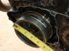
the 003.jpg shows the flywheel and 2.5 " magnet that generates the
reference timing signal when it passes a fixed sensor coil every rev.
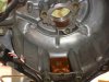
006.jpg shows the sensor coil as seen inside the flywheel cover
dr eXntrik -
hi. what you are trying to do is a project i have been with for my motorcycle
for the past year.
its a 225 yamaha and the analog ignition circuit died. and is being updated
with a digital one. the hard part is coming up with a coded micro-controller
to handle the spark plug firing. this has become a DIY matter. as none of
any other postings anywhere were enough help to understand / get me going.
this has had me dive into learning Microchip assembly language. MPLAB IDE
v. 8.92 is the s/w ... and its been a slow process. an enjoyable one though.
the cdi circuit board to handle the spark was bought as a kit. and it will just
need some work to fit the available space on the bike.
my estimate is another month or two for the code to be finished.
for any other engine the code will have to be edited to fit that engine's
timing curve. and once you get how the code works it wont be too much
of a problem.
there are so many details to a project of this sort. and i will be happy to
share what has been learned. let's start with what you think is the place where you
want to begin
regards.
bob
the 003.jpg shows the flywheel and 2.5 " magnet that generates the
reference timing signal when it passes a fixed sensor coil every rev.
006.jpg shows the sensor coil as seen inside the flywheel cover
Hey,dr X ,
hi. gads , you've got a load of bikes to work on. this is going to be one major project for you.
your interest and enthusiasm is most welcome. i was half afraid you'd want to do the code
in C. god forbid. then we'd never be able to move along and understand each other.
lots of people eat that language up tho. a higher level language was ruled out early on as , like
trying to use a basic stamp or the picaxe series ... one just never knows the timeline of
the program execution. while with assembly you know to the microsecond what is going on.
plus the MPLAB IDE s/w even has a timing tool. you can use it to find out how long execution
between 2 points in the code takes.
one thing that came to mind since last writing is that altho my yamaha is a 4-cycle the code
should work on a 2-cycle with no changes. this is due to the code doing the same thing
every rev and firing every rev too. but only one firing does any good. the wasted spark
happens during the exhaust phase.
here's an important link for you :
http://gooligumshopcom.fatcow.com/shop/gooligum/tutorials/PIC_Intro_0.pdf
from the time my yamaha died and i got going with assembly learning was an
agonizing 4 months dealing with the matter of what to do and how. with some
major luck i found an organized series of lessons on learning to code in assembly.
they were well written and bite-size. and progressive too. plus being free didnt hurt
either. the biggest mistake i almost made was to buy somebody's s/w. namely
the 'PicBasic Pro' that melabs.com sells. that would have been further pain added to
a very stressful time.
with david m's lessons , a Pickit-2 programmer and Microchips 'LPC' demo board
i was set. as david's lessons are written for the LPC board. and the training board
that he sells. had i to do over again i'd a bought his pic training board.
8.92 is the version of MPLAB in use now. but it is not the ver started with.
that one was 8.62 i think . not sure now. and it didnt matter anyway.
also his lessons intro you to some 'X' ver of MPLAB. i avoided those pages.
and wish he'd of done a 2'd set of lessons to omit the distraction.
the first lesson in the 'baseline' series , the ones that are free , will intro you
to using MPLAB and creating a program via the wizard feature. this was a big
hurdle for me. and took a month to figure out. even for code that does nothing
more than lite a led.
once you get how to use the MPLAB template files for the lesson 1
pic 12F508 , 509 and write a piece of code, build it , fix errors, then run it
and save the code for later you are on your way.
looking back i think everything i needed to know for the ignition code
program under dvp was learned in the first 4 or 5 or 6 baseline lessons.
my goal then and now has been to do the code with the simplest
pic chip, in a way that is plain jane. and therefore more understandable
by other beginners. later versions can get fancy. and likely will in a
natural way as other methods are thought of and learned.
at this point the final code version will be in either the 508 or 509 pic .
they differ in only program memory space. 512 or 1024 ml's.
since i'm not there yet with a working program it is still an unknown
how many divisions to make of the timing curve. like if the range
is in units of 100 RPM's vs 500 the code will need more room.
this is where testing will have to be done.
and listen to how the engine sounds with these jumps in timing
to stop for now.
next post will include a link to the CDI kit.
all totaled to get the cdi kit, a Microchip LPC demo board or the Gooligum pic
training board and a Microchip Pickit-3
programmer will cost in the 200-300 range.
bw