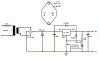
There are a number of problems with that schematic. I'd be interested to know where you got it from.
The second 9V battery, labelled V3, that provides the -9V rail for pin 11 is not needed because the LM324 is single-supply-compatible - pin 11 can be connected to the ground rail of the circuit. This change will save you a lot of hassle.
The "1V battery" labelled V1, connected to pin 3, is not a practical suggestion; it simply means that pin 3 should be provided with a 1V reference voltage. In practice it should be replaced by a voltage reference such as a TL431 (Texas Instruments, also second-sourced by various other companies with a different alphabetic prefix but the same number, 431). This device's voltage is 2.5V (nominal) so you'll need to use a voltage divider to reduce this voltage, because with this design, the voltage on pin 3 must be at least somewhat lower than the lowest output voltage you need. You can use a divider of 15K and 10K to drop 2.5V down to 1V as specified in the original diagram. The TL431 needs a current source, normally just provided from the positive supply rail through a resistor. Get a data sheet from
www.ti.com or Digikey.
The circuit can only deliver around 10 mA because the op-amp output is unbuffered, and small op-amps like the LM324 aren't designed for high current output. You can add a transistor or MOSFET to increase the current output capability. The simplest option is a power Darlington NPN like the TIP120/122. Connect it between the op-amp output and the rest of the circuit, with the op-amp output to the base, emitter to the rest of the circuit, and collector to the main positive supply rail. It will need a heatsink. Power dissipation in the transistor is equal to the voltage across it (in volts) multiplied by the current through it (in amps). Maximum power dissipation will be when it's delivering 1.5V at 2.5A. If your input supply rail is 18V, voltage across the transistor will be 16.5V and current will be 2.5A so dissipation will be around 40W. To keep the transistor temperature below say 100 degrees Celsius at an ambient temperature of 25 degrees Celsius, you'll need a heatsink with a thermal resistance of about 2 degrees Celsius per watt (75/40). This is not a small heatsink. A switching power supply would be a good way to reduce power dissipation, since they are much more efficient than a linear regulator, especially when the output voltage range is wide. You really need to pay attention to layout when using them, though, and ideally use a printed circuit board. It might be a good idea to look for switching supply boards already made up - these are available from Chinese retailers and on eBay I think. The changes to add the features you need would be pretty minor, and these supplies have built-in current limiting.
The circuit has no current limiting. If the output is shorted out, the circuit is not designed specifically to limit the current it tries to deliver. With no buffer on the op-amp output, the current was supplied by the op-amp itself, which will limit it to around 20 mA (give or take), and a shorted output will make the LM324 get hot and possibly lose its magic smoke. If you add a buffer transistor, and use a power source that can deliver 2.5 amps or more, a shorted output could cause a heavy and uncontrolled current to flow, unless you provide some kind of current limiting. There are various ways to implement current limiting. I (or someone else here) will to into detail later, since I don't have that much time now.
Both of the potentiometer values are wrong. The resistances in the feedback circuit (all the resistances in the original schematic) are chosen so that when the output is at the voltage you want, the voltage on pin 2 (which is set by those resistances) will be equal to the voltage on pin 3, which is 1V from the voltage reference and voltage divider.
Because R9 is 1 kilohm, the current in R9 is 1 mA (I = V / R; V is 1V and R is 1000 ohms so I is 1 mA), and every 1 kilohm of feedback resistance will add 1V to the 1V output "base" voltage.
The five suggested values for the feedback resistors (R1~5) are close to the calculated values but the exact values are a bit strange. I don't know why the designer specified a 10977 ohm resistor; you won't be able to buy one! It would be simplest to make up the exact values by putting resistors in series and/or parallel. Also instead of having a separate resistor for each voltage, it's simpler to put the resistors in a chain, and connect the rotary switch to different places in the chain according to the desired output voltage. This means that you'll only need three different resistor values, instead of five.
If the potentiometers are supposed to add 0.1V and 0.05V then their values should be 100 ohms and 50 ohms respectively. These are at the low end of the spectrum for carbon potentiometers. You could scale up all the resistor values in the feedback circuit by a factor of ten and use 1 kilohm and 500 ohm potentiometers.
Potentiometers don't have a very accurate end-to-end resistance; typically it's around +/- 20%. If you don't mind that they don't add exactly the desired amount of voltage, then that's fine. If you do, there are ways to fix this problem that I can get into later.
Finally, you should make sure that the rotary switch is a shorting type. That is, as you turn it, the common contact connects to the next position before it disconnects from the previous position. If there is a gap during which the common contact doesn't connect to anything, the circuit's output voltage will jump up to the maximum possible voltage (about a volt less than the input supply voltage) as you rotate the rotary switch. If a load is connected at the time, it could be damaged by the high voltage glitch. Luckily, almost all rotary switches are the shorting type, but you should make a note on the schematic because it is a requirement of the circuit.
I would be happy to help with the circuit. Can you describe what you want to use it for, what you're planning to use as the input power source, and what constraints you have. Also please consider using a pre-made switching power supply (you can get these rated for 3A output, and they're not expensive) since they can probably be modified pretty easily to do what you want. Go for one that is already adjustable.

")