Do you mean the motor voltage?
I'm pretty sure this is not what
@Bluejets meant. Obviously you expect a logic High level at the B-input of the drv chip - whatever this input is.
But you get only 0.2 V (post #17). This has absolutely nothing to do with the motor voltage or the reference voltage.
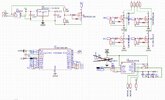
By the way: you really need to be more concise. In your schematic the inputs of the drv-chip are IN1 and IN2, there is no "B-input". Also be careful which pins are inputs or outputs. Otherwise you leave us perplexed.
Separately everything seems to work fine,
Looks like the output of the attiny is overloaded and therefore can't drive the drv-chip to a logic High level. This can happen when the current from the output of the attiny to the drv-chip is too high. Without the drv-chip there is no current and then the attiny can drive the output to logic-High.
the other (input B) cannot be controlled at all and is constantly pulled down, probably by the integrated pulldown resistors of the drv.
This is unreasonable. The pull-down resistor is 100 kOhm, this will not overload the Attiny's output. If it would, the same thing would happen to the other input, which it doesn't.
On the pcb it is correctly wired.
As much as you may dislike it, a fault in the wiring on the PCB is a real possibility. Have you checked that the outputs of the attiny are not short-circuited to any other signal or supply voltage? Even if the design is correct, a fault in the manufacturing process may leave a very thin trace that creates a short circuit.
What happens, wehn you remove the attiny, then connect a 5 V supply voltage to the signals PA2 or PA3 (not simultaneously, one after the other)? I assume you have a multimeter and can measure the current going into these signals ?