Maker Pro
Maker Pro

Attiny1606 burning out when controlling a drv8251

lavaman

Apr 20, 2024
10
Joined
Apr 20, 2024
Messages
10
Hi, I am designing my own locomotive DCC decoder, no need to know what that is. The major problem i am having now is that if i try to use the drv8251 the attiny1606 overheats and then burns out. Even when there is nothing connected to the output, i was just measuring the output voltage with a multimeter. Initially, everything was fine, but then, as i said, the mcu burnt out. The drv is using the reference voltage of the attiny, plus those resistors on the inputs should prevent possible overcurrent. Prior to assembling the whole PCB, I tested all the parts individually. First the voltage regulator, then separating the signal. And last i tested the drv. For the test, i used the same schematic for the drv as shown in the picture before, but instead of the attiny I was controlling it with arduino nano (vcc 5v). That seemed to work with no problem
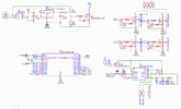
EasyEDA(Standard) - A Simple and Powerful Electronic Circuit Design Tool - Google Chrome 20.04...png
 

Bluejets

Oct 5, 2014
6,948
Joined
Oct 5, 2014
Messages
6,948
Seems quite a lot of info missing from your circuit diagram which only introduces further questions for an overall view.
Specs for the DRV8251 say supply voltage starts at 4.8v.
What is Q1 supposed to do?
 
Last edited:

Delta Prime

Jul 29, 2020
1,990
Joined
Jul 29, 2020
Messages
1,990
Hi, I am designing my own locomotive DCC decoder, no need to know what that is
Then we shouldn't know what what the acronym DCC means? So in that spirit we shouldn't bother with the fact that DCC's have sub classifications called a mobile decoders or what the NMRA refers to as multifunction decoders, and then there is function decoders and accessory decoders. Multifunction decoders can be further broken down into retail and OEM.
Overvoltage problems could be that the booster is set to incorrect scale.
Current draw exceeds decoder ratings (wiring short or another overload condition). Poor wiring can cause this. That's how you get runaway trains.
But since I don't know what a DCC is I cannot help you...


danadak

Feb 19, 2021
780
Joined
Feb 19, 2021
Messages
780
Is that a 1 ohm R between Attiny outputs and MOSFET gates ?

Should me more like 20 - 50 ohms.

Can you drive one of your mosfets with Nano and look at outputs of
Nano with a scope, single shot trigger, edge detect, try both Vdd
+ .5 as a trigger and also Vss - .5 to see what transients you are getting.
Also look at Vdd on Nano.

What is load of the MOSFETs ?

Note a multimeter cannot detect transients in the typical time range
transients are experienced in MCO systems. Scope is almost mandatory.

Bypass on ATTINY85 Vdd should also include a ceramic, say .1 uF, to handle
high freq noise and transients.


Regards, Dana.
 

Harald Kapp

Moderator
Moderator
Nov 17, 2011
13,748
Joined
Nov 17, 2011
Messages
13,748
Then we shouldn't know what what the acronym DCC means?
Digital Comman Control for e.g. model railways.

The problem is probably the MOSFET Q6. It turns off the GND connection to the DRV8251. Therefore when GND is turned off, the whole DRV chip floats to V+. With V+ >> 5 V (12 V or so for a model railroad?), this can "backfire" into the Attiny and destroy it.
Connect the DRV chip permanently to GND with a fixed connection. To turn the DRV chip off, use the control inputs or switch V+ - not GND.
 

danadak

Feb 19, 2021
780
Joined
Feb 19, 2021
Messages
780
I cannot find the max injection current permitted in Atmel parts
to prevent triggering the parasitic SCR structure that is a part
of the GPIO port pin inherent in all non isolated CMOS parts
(pretty much all standard CMOS). This will cause latchup in a
CMOS part if triggered, typically fusing open 1 or more bond
wires from leadframe to die inside part. Google "CMOS latchup"
or "CMOS injection current".....

Your 6.8K R's you placed in series probably too low a value.
This all depends on current level to trigger the SCR,
and reported from various CMOS << 1 mA in some cases.
But you cannot make them too large as they will adversley
affect timing.


Kapp I think hit the nail on the head.

Regards, Dana.
 

Harald Kapp

Moderator
Moderator
Nov 17, 2011
13,748
Joined
Nov 17, 2011
Messages
13,748
my own locomotive DCC decoder, no need to know what that is.
That is your opinion. The backside of not knowing what DCC is that one doesn't know that V+ in your circuit is way higher than 5 V, more like 12 V or so. Which is important for the failure observed.
 

lavaman

Apr 20, 2024
10
Joined
Apr 20, 2024
Messages
10
thanks for your answers. After some iterations thanks to your recommendations the attiny completely stopped overheating and the circuit is working absolutely fine. But for one fatal exception, the attiny doesn't seem to be able to switch the B input of the drv high. Not sure why tho. All i have done was, directly connect ground to the drv and add 1k ohm resistors between the attiny and input of the drv. One of the inputs can be controlled fully, but the other (input B) cannot be controlled at all and is constantly pulled down, probably by the integrated pulldown resistors of the drv.
 

danadak

Feb 19, 2021
780
Joined
Feb 19, 2021
Messages
780
Input 1 and 2 of DRV8251 have 100K ohm pulldowns. So 1 K from ATTINY dominates the
logic level on pin.

You have the ATTINY85 pin configured properly ? Strong drive.....config.


Regards, Dana.
 

lavaman

Apr 20, 2024
10
Joined
Apr 20, 2024
Messages
10
Yes the attiny is configured and working properly. When testing without the drv installed on the board, both inputs are working just fine.
 

Harald Kapp

Moderator
Moderator
Nov 17, 2011
13,748
Joined
Nov 17, 2011
Messages
13,748
WIth the drv installed, what is the voltage on the output pin of the controller and the input voltage to the respective pin on the drv-chip? They should matvh closely. If the input voltage of the drv-chip is noticeably less than the output voltage of the controller, check the series resistor. You might have grabbed a much higher value instead of the intended 6.8 kOhm.
Or simply try a much smaller value, e.g. 1 kOhm instead of 6.8 kOhm.

If the resistor is o.k. and there is still a noticeable voltage drop, or if there is no voltage drop, the input pin of the drv chip may be defect. this could be a result of the current going from the drv-chip to the controller in your previous experiments. Do you have a new drv-chip to test this scenario?
 

lavaman

Apr 20, 2024
10
Joined
Apr 20, 2024
Messages
10
When the attiny output coresponding to the faulty drv input, is set high the voltage is around 0,2v. And the coresponing drv output is also 0.2v or little higher (0,2-0,3v). For this new test i installed complete set of new components, just to be sure.

The resistor installed is 6k8, but in later test i removed it completely.

Motor voltage in these test was 5v, with the intended voltage (16v) results are the same. No damage done to the circuit and the motor can ne controlled one way.
 
Last edited:

Harald Kapp

Moderator
Moderator
Nov 17, 2011
13,748
Joined
Nov 17, 2011
Messages
13,748
When the attiny output coresponding to the faulty drv input, is set high the voltage is around 0,2v.
0.2 V is, obviously, not High but Low.
If the output goes to ~ 5 V without the drv-chip connected, either the drv chip is faulty or your wiring. I'd suspect your wiring. Your schematic shows an inconsistency: signal PA2 is connected to pin PA4 and pin PA2 thus the outputs of PA2 and PA4 may conflict. Remove signal PA2 from pin PA4.
 

lavaman

Apr 20, 2024
10
Joined
Apr 20, 2024
Messages
10
In the schematic it is wrongly marked. On the pcb it is correctly wired. Signal on PA2, and inputs of the drv on PA3 and 4. The wiring should be fine.

I did test the drv chip i am using. Connected to Arduino nano (Vm 11.1V and Vref 5v) it works just fine.
 
Top