Maker Pro
Maker Pro

Analog Voltage recognition by Microcontroller ADC

Surjitsinh

Jan 1, 2015
17
Joined
Jan 1, 2015
Messages
17
Hi,

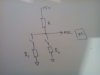
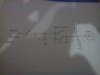
I have a voltage divider circuit as Shown in Image 1, To get different voltage drop based on closed switch and it is recognised by the ADC of a micro controller. Now if I am generating analog voltage from PWM signal as shown in Image 2 but ADC does not recognised the change?

I get the exact analog value at input pin of ADC based on the duty cycle.

Please give your views.
 

Attachments

  • Image 1.jpg
    Image 1.jpg
    101.8 KB · Views: 83
  • Image 2.jpg
    Image 2.jpg
    107.5 KB · Views: 105

(*steve*)

¡sǝpodᴉʇuɐ ǝɥʇ ɹɐǝɥd
Moderator
Jan 21, 2010
25,510
Joined
Jan 21, 2010
Messages
25,510
Depending on the value of the R and C in the input low pass filter, it may take some time for the voltage to settle at the final value, or it may have some ripple left on it.

Are you looking for a specific value from the adc, or a value in a small range?

What value are you expecting and what are you getting?

The resistors on the output of the op-amp are not necessary.
 

Bluejets

Oct 5, 2014
6,958
Joined
Oct 5, 2014
Messages
6,958
If the resistors in fig 1 are appropriate levels and you wrote the program correctly, it should work ok.
 

Surjitsinh

Jan 1, 2015
17
Joined
Jan 1, 2015
Messages
17
Hi

Thank you for your reply. I want to have 0-2V output but in Steps e.g 0V, 0.5 V, 1V, 1.5V and 2V. As shown in the Image 1 if I use simple voltage divider ADC recognised the Voltage. But when I connect it with Voltage follower output. ADC does not recognise the change. R = 10K and C = 10uF, PWM freq = 5khz
 

Bluejets

Oct 5, 2014
6,958
Joined
Oct 5, 2014
Messages
6,958
In that case would it not be better to count the frequency pulses ?
 

Surjitsinh

Jan 1, 2015
17
Joined
Jan 1, 2015
Messages
17
In that case would it not be better to count the frequency pulses ?
Not possible because MCU is fixed and need Analog voltage from 0-2V. I have a PWM source so I thought to use it to generate analog voltage than using resistor divider circuit. So I could control the voltage with Duty cycle.
 

Surjitsinh

Jan 1, 2015
17
Joined
Jan 1, 2015
Messages
17
Hi,

I have connected the circuit as shown in Image 2 it works fine only issue I face now is there is too much current out of Op-Amp output. if I use a resistor I will drop some voltage. Please suggest a way out.
 

BobK

Jan 5, 2010
7,682
Joined
Jan 5, 2010
Messages
7,682
Yes, get rid of the superfluous resistors at the output.

Bob
 

(*steve*)

¡sǝpodᴉʇuɐ ǝɥʇ ɹɐǝɥd
Moderator
Jan 21, 2010
25,510
Joined
Jan 21, 2010
Messages
25,510
HI Bob,

Yes I have removed those resistors and used a series resistor to limit the current. Flowing inside The Microcontroller.

That will make the voltage inaccurate.

Why is there any significant current? Does the output of the op amp exceed the supply rails of the microcontroller? Have you mistakenly set the pin as an output instead of an input?
 

BobK

Jan 5, 2010
7,682
Joined
Jan 5, 2010
Messages
7,682
Yes, the input should draw negligible current.
How do you know there is a lot of current drawn from the output?

Bob
 

(*steve*)

¡sǝpodᴉʇuɐ ǝɥʇ ɹɐǝɥd
Moderator
Jan 21, 2010
25,510
Joined
Jan 21, 2010
Messages
25,510
Also, please see post #2. There are some important unanswered questions.
 
Top