Maker Pro
Maker Pro

analog input buffer question

yougarage

Jul 13, 2011
13
Joined
Jul 13, 2011
Messages
13
hello I'm going to make an analog input buffer for a microcontroller.
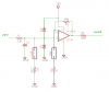
I came out with this solution but I don't know if it's right.
the op amp (rail to rail)is powered from a 5v source

JP1 and JP2 are two jumpers.
JP1 allows me to choose the input range: JP1 installed, 0-12v, JP1 removed, 0-5v
JP2 allows me to change the op amp gain: JP2 installed, gain = 10, JP2 removed, gain = 1
do you think this design could lead me to problems because the resistors R1 and R3 are unuseful with the jumpers removed?
I thought the tlv2371 rail to rail is a good choice for this purpose, what do you think about it?
thanks for your help!
 

Attachments

  • opamp.png
    opamp.png
    25.4 KB · Views: 465

Resqueline

Jul 31, 2009
2,848
Joined
Jul 31, 2009
Messages
2,848
Everything looks good, I can't see any issues at all with anything. Just beware of the need for a 22 ohm output resistor on that op-amp if the uC input is greater than 10pF.
Needless to say, but just for reference, you'll get a 12.5V input range with JP1 installed, and respective input ranges becomes 1/10'th with gain = 10 (JP2 installed).
Also keep in mind that input filtering can be useful to avoid any signals aliasing with the sampling frequency.
 

yougarage

Jul 13, 2011
13
Joined
Jul 13, 2011
Messages
13
thanks for your hints!
and yes,I thought I need a low pass filter.
I 'm reading slow varying signals like ntc resistors but I need to remove some noise
can I connect a capacitor right after R1 to Ground to create a rc filter or it could be affected by the voltage divider sharing the same resistor (R1)?
what do you mean about the uC input? is there a capacitance to play with?
thanks a lot
for a novice like me your advices are invaluable
 

poor mystic

Apr 8, 2011
1,074
Joined
Apr 8, 2011
Messages
1,074
All electronics devices have some capacitance. :)
Capacitance is intrinsic to the operation of the uC, because gate capacitance plays a very important part of the operation of MOS transistors. The input transistors' gate capaitance will be specified on the device data sheet from the manufacturer.
 

yougarage

Jul 13, 2011
13
Joined
Jul 13, 2011
Messages
13
Perfect now I understand! :)
So this should be my final layout.(see attachment)
As a further safety feature, I want to add a zener diode to prevent the input voltage going over the op amp maximum rating.
Now, can the zener affect my voltage divider? does it act as a resistor in the normal voltage range?
maybe I should lower the R1 value?
I also attached a part of the zener datasheet, is there a value to use to calculate this?
I underlined the zener I need, clamping voltage at 16 v.
 

Attachments

  • forum2.png
    forum2.png
    19.5 KB · Views: 344
  • zen.jpg
    zen.jpg
    60.7 KB · Views: 232

Resqueline

Jul 31, 2009
2,848
Joined
Jul 31, 2009
Messages
2,848
The 16V zener has a leakage current of 0.5uA at 11V which could set up 1.65mV across the 3.3k resistor. A 100k source impedance could get a 50mV error.
But that's at 11V, which is way above the 5V supply anyway. The spec' says the inputs are allowed no more than 0.2V outside the power rails, and can take 10mA.
A maximum input current of 10mA means you can have up to 33V across the 3.3k resistor, for a total input safe range of -33V to +38V using no extra protective parts.
If you want to further augment the input protection you could use Schottky diodes connected as in the diagram below. They also have a leakage current btw..
 

Attachments

  • forum3.PNG
    forum3.PNG
    12.6 KB · Views: 851
Top