First of all, I still havent rebuild my first circuit yet, as I have not the time to do so. Right now, I'm only trying to find a way to produce true linearity for my fist circuit. I like discrete stuffs, I am learning so much more about transistors this way.
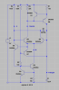
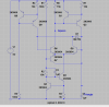
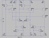
Anyway here is what I came up with: Version 4

1. No more current mirrors!
2. Sharp square wave to trigger current source.
3. Added current sense transistor Q2 to monitor and correct Q5's base current
4. Added schottky diode across Q6's base and collector to prevent it from saturating (This solved the problem of non-linear discharging)
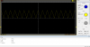
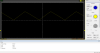
I think I've nailed it! Although at higher frequency, changing cap to 1nF, distortion begins to show, might have to shove a little more current into it.
Anyway, thats it for now. Thanks to all who have been following this thread, and to KrisBluesNZ + CDRIVE who have been responding and thus providing encouragement to further explore
As always, please provide feedback!