Maker Pro
Maker Pro

Upper frequency limit of an oscillator

Akshatha Venkatesh

Jan 14, 2017
145
Joined
Jan 14, 2017
Messages
145
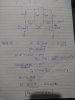
I have an astable multivibrator circuit , which operates as expected only upto a certain frequency. To increase the oscillation frequency, if I increase the base resistors or decrease the capacitors , the oscillation completely stops. What could be the reason ? How do I go about analysing what the maximum frequency could be from the multivibrator output?
 

Harald Kapp

Moderator
Moderator
Nov 17, 2011
13,748
Joined
Nov 17, 2011
Messages
13,748
It certainly helps if you post a schematic of your circuit and tell us
- up to which frequency does the oscillator work?
- what is the frequency you want to achieve?
 

Akshatha Venkatesh

Jan 14, 2017
145
Joined
Jan 14, 2017
Messages
145
It certainly helps if you post a schematic of your circuit and tell us
- up to which frequency does the oscillator work?
- what is the frequency you want to achieve?
I want to achieve around 300kHz, but for the above values there are no oscillations, for 150k , I'm getting about 180khz.
 

Attachments

  • IMG_20180605_143651.jpg
    IMG_20180605_143651.jpg
    189.9 KB · Views: 78

Harald Kapp

Moderator
Moderator
Nov 17, 2011
13,748
Joined
Nov 17, 2011
Messages
13,748
Your capacitors are very small. Usually larger capacitors and smaller resistors are preferable to provide enough base drive current to the transistors. Check this website which has a useful table of suitable compoent values.
 

Akshatha Venkatesh

Jan 14, 2017
145
Joined
Jan 14, 2017
Messages
145
Your capacitors are very small. Usually larger capacitors and smaller resistors are preferable to provide enough base drive current to the transistors. Check this website which has a useful table of suitable compoent values.
Take a look at my circuit and calculation below, if I reduce the resistance, I can't get the oscillations. I also simulated the above circuit with the same component values in LTspice, it works.
 

Attachments

  • IMG_20180605_192627393.jpg
    IMG_20180605_192627393.jpg
    168.5 KB · Views: 57
  • IMG_20180605_192621897.jpg
    IMG_20180605_192621897.jpg
    184.7 KB · Views: 56

BobK

Jan 5, 2010
7,682
Joined
Jan 5, 2010
Messages
7,682
That's not what you said before, you said if you increase the resistance it would stop oscillation. So only 1 value of resistance oscillates? I guess you were lucky to find it.

Bob
 

Akshatha Venkatesh

Jan 14, 2017
145
Joined
Jan 14, 2017
Messages
145
That's not what you said before, you said if you increase the resistance it would stop oscillation. So only 1 value of resistance oscillates? I guess you were lucky to find it.

Bob
Take a look at my calculation
 

Harald Kapp

Moderator
Moderator
Nov 17, 2011
13,748
Joined
Nov 17, 2011
Messages
13,748
I also simulated the above circuit with the same component values in LTspice, it works.
A simulation is only a limited image of reality.
Take a look at my circuit and calculation below
The calculation is correct in terms of getting a value for C in terms of f and R. However, you'll have to take into account the physical behavior of the components, too. With a base resistor of 140 kΩ and a supply voltage of 5 V you get a base current into the transistors of Ibase ~(5 V-0.6 V)/140 kΩ = 31 μA. Assume a gain of 100 for the transistor, then you get a collector current of Ic = 100 * 31 μA = 3.1 mA. 3.1 mA will drop Vdrop = 3.1 mA * 500 Ω = 1.55 V.
The transistor's collector emitter voltage will be Vce = 5 V - Vdrop = 3.45 V. The transistor is not in saturation.

But the derivation of the equations you used assume that the transistor are in saturation, Therefore you need to decrease the base resistor's values or increase the collector resistor's values.
 

Akshatha Venkatesh

Jan 14, 2017
145
Joined
Jan 14, 2017
Messages
145
But why assume gain as 100 ? And when I increase the collector resistor values , it doesn't work , no oscillation. If I increase Rc, Ic would decrease , in-turn Ib would decrease and hence the transistor stops switching on. This was my reasoning. Could you please explain where I'm wrong.
 

Harald Kapp

Moderator
Moderator
Nov 17, 2011
13,748
Joined
Nov 17, 2011
Messages
13,748
But why assume gain as 100 ?
Because that is a typical value for small signal transistors. Look up the datasheet of the transistor you use to get a better value. Note that the gain can vary widely.
If I increase Rc, Ic would decrease , in-turn Ib would decrease and hence the transistor stops switching on.
No. If you increase Rc, the same collector current will create a higher voltage drop across Rc, thus less voltage drop across the transistor. Saturation is an operating mode of a bipolar transistor where Vce < Vbe (see here).

What specific type of transistor are you using? It may simply not be suitable for 300 kHz operation.
 

Akshatha Venkatesh

Jan 14, 2017
145
Joined
Jan 14, 2017
Messages
145
Because that is a typical value for small signal transistors. Look up the datasheet of the transistor you use to get a better value. Note that the gain can vary widely.

No. If you increase Rc, the same collector current will create a higher voltage drop across Rc, thus less voltage drop across the transistor. Saturation is an operating mode of a bipolar transistor where Vce < Vbe (see here).

What specific type of transistor are you using? It may simply not be suitable for 300 kHz operation.
BC846B- NPN general purpose transistor. How do I determine if a certain transistor is suitable or not for 300kHz operation.
 

Harald Kapp

Moderator
Moderator
Nov 17, 2011
13,748
Joined
Nov 17, 2011
Messages
13,748
The BC846B has a DC current gain between 200 and 450.
The transit frequency (where gain passes below 1) is >=100 MHz, therefore 300 kHz should pose no problem.

Are you sure you have all connections correct?
 

Harald Kapp

Moderator
Moderator
Nov 17, 2011
13,748
Joined
Nov 17, 2011
Messages
13,748
Did you double check the pinout of the transistors?
 

BobK

Jan 5, 2010
7,682
Joined
Jan 5, 2010
Messages
7,682
From playing around in LTSPICE, you need much lower collector resistors. Try 100Ω.

Highest I could get is about 1.2MHz using the following:

2N3904

Rc: 77Ω
Rb: 5K, 56K (they have to be different for it to oscillate in LTSPICE)
C: 400pF

Bob
 

Audioguru

Sep 24, 2016
3,656
Joined
Sep 24, 2016
Messages
3,656
Maybe it is built on a solderless breadboard and its stray capacitance between all the rows of contacts and wires and inductance of its many long wires prevent the very low value capacitors and very high value base resistors from working properly. Make it with a compact pcb layout using capacitors and resistors with reasonable values as shown in the article.
 
Top