Maker Pro
Maker Pro

Replacing upper board with pot. for treadmill motor speed control.

HazMatt

Sep 4, 2017
5
Joined
Sep 4, 2017
Messages
5
20170904_152610.jpg 20170904_152509.jpg 20170904_151601.jpg 20170904_143838.jpg Hi everyone.
Im brand new to the forum and know nothing of electronics.
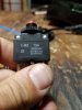
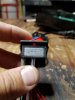
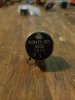
I have a treadmill motor i plan to use for a belt grinder but don't want the bulky display and original buttons/ controls. I do have everything from original set up and motor works with all the factory wiring.
I want to switch to an analog potentiometer for speed control to eliminate the upper (treadmill display) board but don't know if the motor control board will work independently of it.
I Will appreciate knowledge sharing. Thanks for looking. HM.
20170904_152610.jpg
 

Attachments

  • 20170904_152015.jpg
    20170904_152015.jpg
    207.4 KB · Views: 88
  • 20170904_152006.jpg
    20170904_152006.jpg
    188 KB · Views: 116

Minder

Apr 24, 2015
3,478
Joined
Apr 24, 2015
Messages
3,478
Looks like J1 is the control input, it could either be a variable linear pot style input or a PWM signal,
You could try a 5k -10k pot first to see if it works.
M.
 

HazMatt

Sep 4, 2017
5
Joined
Sep 4, 2017
Messages
5
20170904_152501.jpg
Looks like J1 is the control input, it could either be a variable linear pot style input or a PWM signal,
You could try a 5k -10k pot first to see if it works.
M.
Looks like J1 is the control input, it could either be a variable linear pot style input or a PWM signal,
You could try a 5k -10k pot first to see if it works.
M.
Nice. I guess if the pot doesn't work, I'm stuck with the original board then correct? Thanks for the quick response Minder.
 

HazMatt

Sep 4, 2017
5
Joined
Sep 4, 2017
Messages
5
20170911_215415.jpg 20170911_215415.jpg

I tried various combinations of connections between pot and j2 terminal, no dice.
 

Attachments

  • 20170911_215408.jpg
    20170911_215408.jpg
    197.4 KB · Views: 92

HazMatt

Sep 4, 2017
5
Joined
Sep 4, 2017
Messages
5
The PWM may be the answer then?
M.
May be. With my infantile grasp on electronics and no circuit building experience I feel it will be more direct to use the existing controls. However, now I'm super curious and want to build that circuit.
That's all I need is another hobby! Any one stop shopping for sourcing the components ?
 

Minder

Apr 24, 2015
3,478
Joined
Apr 24, 2015
Messages
3,478
My go-to source is Digikey, next day air delivery to Canada.
There are ones on ebay for $1.50, you could strip the unwanted power components off and just use the 555 circuit only if you just wanted the PWM controller part only to play around with.
M..
 

Alec_t

Jul 7, 2015
3,591
Joined
Jul 7, 2015
Messages
3,591
The original control board ensures the motor speed ramps up from zero at power-up as a safety feature. Do you want/need to replicate that feature?
 

Minder

Apr 24, 2015
3,478
Joined
Apr 24, 2015
Messages
3,478
That reminds me, most that use a pot, that requires that it has to be zero when the units is powered for the speed pot to work.
Did you ensure it was zero when you tried it with the Pot?
M.
 

IamJatinah

Oct 28, 2014
17
Joined
Oct 28, 2014
Messages
17
Hi All,

This looks to be a digitally driven controller, it shows a single TRX pin. Not a good choice for the project.
I may have a decent controller for up to 2hp PMDC that would require a PWM to drive it neatly, but easy to configure.
The only "pot" friendly DC controller I know in treadmills is the KB Drive used in Landice L7 units.

Looks like there is a Prom on your board that recieves serial data and generates a pwm thru the small 4-pin opto maybe

KB Drives is still around, the KB111 maybe it is, can be driven with a 2k-pot on the board itself, but isolated(the board is NOT isolated from AC wall, as are most motor drive rails/controllers) with a knob, or a pwm.

Good luck, look me up if you'd like to try a controller that will work with a pwm control (ttl-level) ;o)
 

Minder

Apr 24, 2015
3,478
Joined
Apr 24, 2015
Messages
3,478
After 5 years, the OP may have moved on from the project! ;)
 
Top