LectricCircuit
- Apr 7, 2017
- 33
- Joined
- Apr 7, 2017
- Messages
- 33
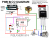
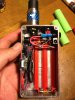
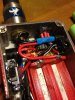
so I made a PWM circuit using a 555 timer. It's to add to my unregulated mosfet mod I use to vape with. I used a 0.1uf ceramic capacitor a 0.01uf ceramic capacitor a 555 timer ic a 1k ohm resistor a 10k potentiometer and 2 diodes (1n4148). These are the exact specs that the schematic calls for that I got off the Internet. I finished it and installed it into my dual series 18650 mosfet mod. Fully charged the batteries are at 8.4 volts. In theory when I turn the pot up to 100 there should be no pulse and it should just be direct voltage from battery and when I turn the pot down the pulse width of 0v should increase and the pulse width of 8.4 volts should decrease. Being that it's switching on and off at a very high speed it will show on a multimeter that the voltage is decreasing as I turn the pot down towards zero. Even though that's not what's really going on. If the pot is turned to 25 this means that in one cycle the mosfet should be off for 75% of the time and on for 25% of the time. The problem I'm having is that For some reason when I have the pot turned up to 100, the output voltage is only at about 3.34 volts even though my multimeter reads the batteries at 8.4 volts. Everything is working. It adjusts the voltage up and down. With pot at zero it's reading 0.64 volts. So I know it's doing its job as far as adjusting the voltage but I have no clue why it would only be 3.4 volts when the pot is turned to 100. At 100 the pot should be completely open allowing the full voltage of whatever the batteries charged to. Thought maybe the resistor was too high so I added another 1k resistor in parallel with the other 1k resistor which would bring the resistance down to 500 ohms but surprisingly the output voltage at 100% went down about 0.2v. Please help. I have the diagram I used attached to this thread. I do not have a scope to test it so I have to work based off logic and theory.