I am doing a Solar powered power bank as my dissertation project. It's based on LT3652 charge control, a Lithium-Ion battery (4500mAh) and 2 boost converters (3.3-5V and 3.3-12V).
I am using a 21W, PV panel with a maximum voltage of 7.68V. I need 4.2V and 2A output to charge the battery.
In calculations I did set minimum voltage in, as 6V and float voltage as 4.2 and followed the datasheet.
My design is based on Sparkfun Sunny Buddy MPPT. I changed the inductor (SDE0805A-100M) and diodes (RBR5LAM30ATFTR) and also sense resistor.
Unfortunately I'm not getting what I need out. Pictures speak better than words.
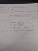
1.My schematic.
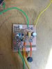
2.The actual prototype board
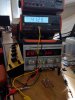
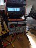
3.The open circuit voltage out. (7V in, 4.2V out)
4.Voltage out with 4.7ohm load.(6V in, 1.5V out . If i change the input voltage any higher and lower than 6V output voltage drops!)
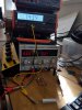
5.Current out with 4.7ohm load.(6V in, 220mA out It goes up to 240mA at 7.6V in).
I appreciate your thoughts and advise as my deadline is reaching and i have been all over the place but i couldn't find the fault. as you can see I have changed the calculated 3.2uH inductor with a 10uH one but it didn't make much of a difference!
Ps. Sorry for the long post, I just wanted to give you as much as information as i can.
I am using a 21W, PV panel with a maximum voltage of 7.68V. I need 4.2V and 2A output to charge the battery.
In calculations I did set minimum voltage in, as 6V and float voltage as 4.2 and followed the datasheet.
My design is based on Sparkfun Sunny Buddy MPPT. I changed the inductor (SDE0805A-100M) and diodes (RBR5LAM30ATFTR) and also sense resistor.
Unfortunately I'm not getting what I need out. Pictures speak better than words.
1.My schematic.
2.The actual prototype board
3.The open circuit voltage out. (7V in, 4.2V out)
4.Voltage out with 4.7ohm load.(6V in, 1.5V out . If i change the input voltage any higher and lower than 6V output voltage drops!)
5.Current out with 4.7ohm load.(6V in, 220mA out It goes up to 240mA at 7.6V in).
I appreciate your thoughts and advise as my deadline is reaching and i have been all over the place but i couldn't find the fault. as you can see I have changed the calculated 3.2uH inductor with a 10uH one but it didn't make much of a difference!
Ps. Sorry for the long post, I just wanted to give you as much as information as i can.
Attachments
Last edited: