Maker Pro
Maker Pro

Help with Scintillator Circuit

NitroEater

Mar 29, 2017
2
Joined
Mar 29, 2017
Messages
2
Hello All,

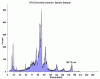
I am working on a project where I want to adapt a Ludlum 3503 Gate Monitor, which checks for and measures radioactivity on truckloads of material, and adapt it so I can get an audio output that can be fed into my laptop and with the aid of software allow me to determine which isotope the scintillator is picking up. There are commercial units like this that you can buy, but they are so expensive that I thought it better to put my "redneck" tendencies to work and come up with my own creation.

What I would like is for someone versed in circuit design to have a look at the circuit and confirm if where I am planning to make the tap is the correct place to get a signal that will give me an accurate facsimile of what the photomultipler has detected. It has to have the intensity that can be converted into pulse height by the software.

Thanks.
 

Attachments

  • M3503may2000-13.jpg
    M3503may2000-13.jpg
    312.5 KB · Views: 81

Alec_t

Jul 7, 2015
3,591
Joined
Jul 7, 2015
Messages
3,591
Welcome to EP!
a signal that will give me an accurate facsimile of what the photomultipler has detected
Depends what you mean by facsimile. As far as I can tell the PM output signal is a ~1.5kV negative pulse with a steep leading edge and a less steep trailing edge. The resulting signal at the inverting input of the comparator is a ~4V rectangular pulse (going from ~ -1.3V to ~ +2.5V) with steep leading and trailing edges and a width approximately that of the PM pulse. In other words the shape and amplitude of the comparator input signal are quite different from those of the PM output signal, although the pulse widths and frequencies are similar.
Here' a sim :-
PhotoMultiplierAmp.GIF
 
Last edited:

NitroEater

Mar 29, 2017
2
Joined
Mar 29, 2017
Messages
2
Welcome to EP!

Depends what you mean by facsimile. As far as I can tell the PM output signal is a ~1.5kV negative pulse with a steep leading edge and a less steep trailing edge. The resulting signal at the inverting input of the comparator is a rectangular pulse going from ~ -1.3V to ~ +2.5V with steep leading and trailing edges and a width approximately that of the PM pulse. In other words the shape and amplitude of the comparator input signal are quite different from those of the PM output signal, although the pulse widths and frequencies are similar.
Here' a sim :-
View attachment 32902

What I'm wanting to do is to end up with a graphical readout that will show the isotopes separated by their heights and KeV qualities. My thinking is that if the signal is tapped before going into the ICM7555 (U3) they would be more or less of the analog flavor. after the ICM7555 (U3) they would be digital. The attached is a readout of Lutetium 176, a calibration isotope. The other is Plutonium. This is what I'm wanting to see as an end result. I may be totally wrong on this assumption, or maybe I need to build an adapter circuit into it.
 

Attachments

  • typical fingerprint.jpg
    typical fingerprint.jpg
    113.7 KB · Views: 93
  • Plutonium.gif
    Plutonium.gif
    9.2 KB · Views: 73

Alec_t

Jul 7, 2015
3,591
Joined
Jul 7, 2015
Messages
3,591
My thinking is that if the signal is tapped before going into the ICM7555 (U3) they would be more or less of the analog flavor.
You lose the 'analog flavor' as soon as the signal gets amplified. I think the best place to tap off would be the base of the first transistor of the amplifier, i.e the R80/CR93 point. That should give you a signal with ~ 1V peak-to-peak amplitude. Whether or not the signal is in the audio range would obviously depend on the PM characteristics and radioactivity levels.

Edit: On second thoughts, further simulation shows that even at the transistor base there can be signal clipping for large input signals, so a better pick-off point would probably be the top of the 47Ω resistor R102.
PhotoMultiplierAmp2.JPG
 
Last edited:
Top