Maker Pro
Maker Pro

Trouble with diffrential amplifier output

paddy

Sep 11, 2012
81
Joined
Sep 11, 2012
Messages
81
Hello,

I am using LM358 op-amp in my circuit.

one op-amp is used as differential amplifier and next is used as an non inverting amplifier.

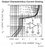
But the problem is the output of the differential amplifier (at pin no.7) is varying from 0.7V to 2.3V and i need it from 0 to 2.3V.

Please suggest!!

attachment.php


thanks,
paddy
 

Attachments

  • ckt.jpg
    ckt.jpg
    16.8 KB · Views: 318
Last edited by a moderator:

CDRIVE

Hauling 10' pipe on a Trek Shift3
May 8, 2012
4,960
Joined
May 8, 2012
Messages
4,960
The first thing that comes to mind is your bridge. Speaking of which, why is the balance pot 10K? Also, getting down to absolute zero on a single ended OpAmp can be difficult.

Chris
 
Last edited:

Laplace

Apr 4, 2010
1,252
Joined
Apr 4, 2010
Messages
1,252
What happens if you substitute 10K resistors for the 1K resistors in the feedback path?

The attached parametric curves should explain why the output does not go below 0.7 volt. In fact it will never go to zero, but will get closer to zero if the output current is lowered.
 

Attachments

  • LM158_Page_07.png
    LM158_Page_07.png
    20.2 KB · Views: 153
Last edited:

paddy

Sep 11, 2012
81
Joined
Sep 11, 2012
Messages
81
Thanks Chris and Laplace for your suggestion!!

With 1K balance pot the output voltage of non inverting amplifier (which is connected to ADC of PIC18F2520) varies from 1.3 to 3.1V.
But as per the datasheet of micro controller theΔVREF of the ADC should be 3V. And with 10K pot it can be achieved. The output varies from 1.4V to 4.4V.

Hello Laplace,

I hv replaced feedback resistors with 10K, But it didn't worked. The output is constant for all the time.

Can you please suggest what i need to do to lower the output current??

thanks paddy
 

duke37

Jan 9, 2011
5,364
Joined
Jan 9, 2011
Messages
5,364
I do not follow what the circuit is intended to do.
The first op-amp is doubling the voltage of the junction of the left two resistors it should output 2.3V.
This is then compared to the output of the pot which presumably is about 2.3/2V

The normal instrumentation amp is to use the first two amps as high input impedance voltage followers and then use the third to subtract these voltages and give gain.
In this case, the source impedance is low and one amp only is necessary.
 

Laplace

Apr 4, 2010
1,252
Joined
Apr 4, 2010
Messages
1,252
I hv replaced feedback resistors with 10K, But it didn't worked. The output is constant for all the time.

Can you please suggest what i need to do to lower the output current??

I suggested the 10K resistors before I looked up the parametric curves for the output sink current. It appears that pin 1 will have a constant 2.3 volts which is fed through the two 1K resistors to the current sink on pin 7. The current is roughly 2 mA. From the sink curves you can see that the current needs to be around 10 uA before the pin 7 voltage will begin to approach zero. (2.3 V)/(10 uA) = 230K ohms. My initial estimate of 10K was off by a small factor. :D
 

CDRIVE

Hauling 10' pipe on a Trek Shift3
May 8, 2012
4,960
Joined
May 8, 2012
Messages
4,960
Is the OpAmp Vcc 24V or 2.4V?

Chris
 

paddy

Sep 11, 2012
81
Joined
Sep 11, 2012
Messages
81
I hv replaced gain setting resistors with 320K and now output varies from 12mV to 1.96V at the output of diffrential amplifier.

Now I hv replaced the two bridge resistors with the sensor.
But when i am increasing the gain of the non inverting amplifier it is not coming back to zero.

For example,
Say I hv given input to my sensor, but the output is not that which i am expecting. So to get the expected output i hv increased the gain of my non inverting amplifier and reached to expected output.

Now if i removed the sensor input, i am expecting zero at the output.

But this is not the case and i am getting some value at the output.

what i need to do???

Thank you very much for the help!!!!!!!!!!!

thanks
paddy
 

CDRIVE

Hauling 10' pipe on a Trek Shift3
May 8, 2012
4,960
Joined
May 8, 2012
Messages
4,960
Try wiring it like this. I get 50mV at TP3. To obtain absolute zero I think you will need to use bipolarity supplies though.

Chris
 

Attachments

  • OpAmpBridge.JPG
    OpAmpBridge.JPG
    22.5 KB · Views: 192

paddy

Sep 11, 2012
81
Joined
Sep 11, 2012
Messages
81
Hello all,

Thanks for help!!!!!!!!

I request to you to have a look on attached circuit.

LM 324 is used with 24 V single ended supply.

This ckt is used in final product. But the problem with this circuit is the output at pin no. 14 is not linear.

At pin 14 the voltage is changing from 56mV to 2.4V. But this change is not linear in accordance with pot movement.

Initially there is sudden rise upto 1V and from 1V to 1.5V it rises too slow and again from 1.5 to 2.4 it rises sharply.

So what i need to do to make it linear?

Thanks,
Paddy
 

Attachments

  • ckt.jpg
    ckt.jpg
    85.7 KB · Views: 159

paddy

Sep 11, 2012
81
Joined
Sep 11, 2012
Messages
81
Also with the same circuit i am unable to get amplified output at pin no.7. I have replaced the feedback resistor with various values but every time i get the output from several milivolts to 0.7V.

But when i use Non inverting configuration it seems working fine.

Please suggest?

Thanks,
Paddy
 

(*steve*)

¡sǝpodᴉʇuɐ ǝɥʇ ɹɐǝɥd
Moderator
Jan 21, 2010
25,510
Joined
Jan 21, 2010
Messages
25,510
I would imagine that you need to tie pin 5 to approximately 1/2 the supply rail.
 

paddy

Sep 11, 2012
81
Joined
Sep 11, 2012
Messages
81
I didn't understand. Can u please explain?

And what can u suggest about the non linear output at pin 14?
 

(*steve*)

¡sǝpodᴉʇuɐ ǝɥʇ ɹɐǝɥd
Moderator
Jan 21, 2010
25,510
Joined
Jan 21, 2010
Messages
25,510
the last op amp has one of its inputs tied to ground. it would be better to use 2 1k resistors forming a voltage divider between the supply rails.

I think you'll find this improves the linearity.
 

paddy

Sep 11, 2012
81
Joined
Sep 11, 2012
Messages
81
As suggested i have tied pin no 5 to 11V through voltage divider and observed as mentioned below.

pin 5 - 11V
pin 6 - changing from 0.6V to 2.6V (Voltage at pin no. 8 changing from some milivolt to 2.3 V)
pin 7 - 6V (constant even if i am changing the pot.)

I have placed 1K resistor in between pin 6 and 8.

Also there is no change in linearity.
:confused:
 

duke37

Jan 9, 2011
5,364
Joined
Jan 9, 2011
Messages
5,364
I still do not understand the circuit!

One 470k resistor goes to an input so there is little current or voltage drop across it. It could be replaced by a wire.
The other 470k goes between the outputs of two op-amps so just provides a load. This could be eliminated.
When this is done, you can see that OpA2 is just a comparator and will have no linearity.
 

(*steve*)

¡sǝpodᴉʇuɐ ǝɥʇ ɹɐǝɥd
Moderator
Jan 21, 2010
25,510
Joined
Jan 21, 2010
Messages
25,510
Correct. An input resistor is required for the last op-amp.

And I see that you have 24V and 2.3V. The voltage divider needs to give you 1/2 of 2.3V approx, not 12V
 

paddy

Sep 11, 2012
81
Joined
Sep 11, 2012
Messages
81
470 K is used in the circuit to get op amp output close to zero.

If these resistors are eliminated i am getting 0.7V at the output.

I expect linear change at buffer output, which is not getting.

I have connected input resistor of 1K at the last op amp..
 
Last edited:

paddy

Sep 11, 2012
81
Joined
Sep 11, 2012
Messages
81
Hello,

Its done!!!!!!

i have tied pin no 5 of inverting amplifier to 1.2V through voltage divider and got the expected output.

thanks for your help!!!!!!!!!!!!!!!!:)
 
Top