Maker Pro
Maker Pro

Transistor hfe

Arouse1973

Adam
Dec 18, 2013
5,178
Joined
Dec 18, 2013
Messages
5,178
Ok I think I have found the issue. It a start up problem. If you give the regulator time to stabilise by adding a RC network after the collector of the pair it works with a 100R. So it must be that the regulators are sensitive to this. This is new to me so I am glad I now know. I think I will email a FAE at ST and ask them to tell me why this happens.
Adam
 

sureshot

Jul 7, 2012
234
Joined
Jul 7, 2012
Messages
234
Ok I think I have found the issue. It a start up problem. If you give the regulator time to stabilise by adding a RC network after the collector of the pair it works with a 100R. So it must be that the regulators are sensitive to this. This is new to me so I am glad I now know. I think I will email a FAE at ST and ask them to tell me why this happens.
Adam
Thanks for doing this Adam. So it needs some unwanted frequency removing during start up.

This makes sense, as i thought nothing of this at first, but when i added and removed loads with both resistor base values, i noticed some odd noises coming from the fan. It was not constant, but would come and go on loading and removing loads. More so at lighter 20 watt loads. But did it at times with a 50 watt load. I noticed the voltage output fluctuated quit wildly when this happened.

But yet at other times i could load the circuit with no unstable output, and a steady output voltage. I'm only guessing here, but i think this is ocillations going on. For the moment i'm going with the more modest MJ2955 transistor. But if times on my side, would like to return to this transistor. It would help if i had a scope for debugging etc. But that's really interesting, thank you for doing that Adam.
 

Arouse1973

Adam
Dec 18, 2013
5,178
Joined
Dec 18, 2013
Messages
5,178
I think it's basically the transistors switching on faster that the regulator has time to settle. When the regulator first powers up the output tracks the input and current limit is at it's maximum. This allow the regulator to supply heavy current on power up. Now in your situation the regulator is getting a higher voltage on the output before the regulator has had time to settle.

But this regulator is not alone, it's actually worse for a LT1083-12. You get 22 Volts on the output.

I have emailed someone I know at Linear Tech.... Lets see what he comes back with.... he may not know exactly what's happening and may have to contact the designer himself if he still works there.

Cheers
Adam
 

sureshot

Jul 7, 2012
234
Joined
Jul 7, 2012
Messages
234
This is interesting, although my knowledge base is limited, i do understand what is going on. I've put out questions in other areas before you started the simulations, and the wise grey beards say the same and similar theorys.

But no one has took this far, so thank you for this. I'm interested to see the out come. It sure was odd behavour with all resistor values i used.

I did think at one point it was running ok with a 50 watt load on it for a day, but when i loaded it lightly, 20 watts, it jumped from 12.2 Volts to 14.1 Volts, dissapointing. But its a learning curve for me.
 

Arouse1973

Adam
Dec 18, 2013
5,178
Joined
Dec 18, 2013
Messages
5,178
I hope the guys at Linear come back with something. Otherwise I will start my own research on the issue. Up until now it's all been educated guesswork. But it will be good to have a definite cause from the guys who design these things. I'll keep you posted.
Adam
 

sureshot

Jul 7, 2012
234
Joined
Jul 7, 2012
Messages
234
I hope the guys at Linear come back with something. Otherwise I will start my own research on the issue. Up until now it's all been educated guesswork. But it will be good to have a definite cause from the guys who design these things. I'll keep you posted.
Adam
Ok Adam Thanks for that.
 

Arouse1973

Adam
Dec 18, 2013
5,178
Joined
Dec 18, 2013
Messages
5,178
Ok so I have had a reply back from the guy at Linear Tech. Basically he is saying that the transistors are not turning off fully to allow the regulator to reach regulation say you have a 1K load. This is the start up current causing the transistors to turn on. Unfortuanatly he didn't go into any depth of why the regulator stops. I guess we would need to simulate the internals of the regulator for that. If I get time I might have a go, but I am on holiday soon so might not get to it for sometime.

I simulated this today before I heard back from him and found that with a light load both the current from transistors and from the regulator start off well, the regulators voltage stops rising quite soon after power up and then the current comes from the transistors and the voltage on the output is the final current through the load divided by the load resistance (Edit: Some current will be entering the regulators output). So with a 1K load you only need 12 mA for the transistors to cause a 12 Volt drop and screw things up.

Now if I put a much lower load say 10R on the output it's fine and regulates to 12 Volts, This is basically because the regulator wins in this case because their isn't enough initial voltage from the transistor on start-up to stop the regulator working. I also tried a 47R and found the transistor could still produce a reasonable current if loaded. I then tried a 22R and found that the transistors were off. I think @AnalogKid mentioned this sort of value and it works.

I don't personally use this sort of circuit but if I did I think what I would do now as a check is disconnect the transistor's collector from the regulator output. Measure the collector voltage and adjust R7 so you have zero volts on the collector. This will ensure that when the regulator starts up with no load it will still regulate.

Adam
 
Last edited:

sureshot

Jul 7, 2012
234
Joined
Jul 7, 2012
Messages
234
I think i got most of that, i will reread again, my memory is naff on med's (illness) but yes thank you Adam ! I will have to mock up a single transistor board version to try this. Really i might just get a breadboard, its long overdue. Since then i have tried 4 x TIP2955's with very good results, although there is a modest voltage drop under load. 12.04 Volts no load, 50 watts load, 11.89 Volts, 100 watt load, 11.73 Volts. A15 Volts regulator could get round this, and drop it 1.5 Volts on the output.

This was already half constructed before i started on the MJ11015 darlingtons transistors. But i will make up another MJ11015 transistor circuit. When it did run with out the regulator doing battle with the transister, it ran very cool and minimal if no voltage drop, compared to the TIP2955's. Thanks again Adam your help is much appreciated !
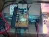
Below 4 x TIP2955's
And running 100 watts, 2 x xbox psu's in series for the input, until i find a decent transformer.
 

Attachments

  • IMG_20160322_233732.jpg
    IMG_20160322_233732.jpg
    231.2 KB · Views: 93

(*steve*)

¡sǝpodᴉʇuɐ ǝɥʇ ɹɐǝɥd
Moderator
Jan 21, 2010
25,510
Joined
Jan 21, 2010
Messages
25,510
That's really interesting Adam.
 
Top