Maker Pro
Maker Pro

Tacx T2240 turbo trainer - blown resistor

MikeMerchant

Sep 19, 2020
1
Joined
Sep 19, 2020
Messages
1
Well I tried replacing the now famous resistor, with a 3W from RS. I tested the MOSFET with a multimeter, it seemed ok, so I didn't replace (at least the diode voltages were ok). I soldered in the new resistor with a small butane iron, which was rubbish. On powering on, I head a 'pop', and nothing else, no lights etc. Again, MOSFET, 1A fuse and resistor tested ok, but it looked like the SMT resistor had not made a good connection. The unit appears totally dead now.
 

lokki

Nov 11, 2020
1
Joined
Nov 11, 2020
Messages
1
Some info for anyone interested,
If you trace the circuit from the live mains terminal there is a 1amp fuse next is a 27 ohm 2 watt wire wound resistor, this is the one that blows apart next is a 3 ohm resistor and finally connected to that is a mosfet

RS numbers 6476188 27 ohm 3 watt
2240070 3 ohm 1 watt
7610689 n channel mosfet 650v 12amp
All in cost about a tenner from rs components. Mine now works. Might be best if you know someone that is experienced in electronics that has the correct soldering kit as the parts are pretty small

Hi, could you advise regarding the parts? I would really appreciate your help.
Same story here with the blown resistor. I've got the following board: Vortex II Smart T2181.25 801761681.
And the blown resistor is 2W 27Ohm (CGS 2W27ΩJ). Next on the board you mentioned 3Ohm resistor - 3R3? Which one? I've got 2 - R57 and R66. Next to R57 is a mosfet: 18N65 M5 GK007626. Next to R66 is a mosfet: B12NK80Z GK1F7 VW CHN 708. Could you advise on the right parts to replace? Uploading the board image for the reference. IMG_5682(2).JPG
 
Last edited:

Geoff Carroll

Apr 23, 2020
3
Joined
Apr 23, 2020
Messages
3
If your trainer is less than 2 years old it is still under warranty. To apply to Garmin (who now own Tacx) you need proof of purchase. They should be able to sort you out.
If your trainer is over 2 years old then they will charge you for replacement of the unit complete. That could cost you upwards of £200 so do your homework!
 

Noendo

Dec 2, 2020
2
Joined
Dec 2, 2020
Messages
2
Hi everyone I'm hoping for a bit of help before giving up.
I also have the T2240 unit that powers up and can connect but the power resistor doesn't work and the power light flashes red and green. I've opened it up to find a coupe of blown resistors one marked "3R3" and the other "CGS 2W6OΩ8J"
I would like to replace these and see what happens but I can't find any for sale. Any help would be greatly appreciated
 

73's de Edd

Aug 21, 2015
3,629
Joined
Aug 21, 2015
Messages
3,629
Sir Noendo . . . . .

Those are being available thru Mouser or Digi Key. . . . . . no-no . . . at a Wally World . .or . . .Auto Zone
I can see the longitudinal long split in the 6.8 ohm unit . . . now, can I assume that the 3.3 ohm surface mount unit is going to be the one closest to the nearby larger power FET, rather than the other slightly smaller Power FET which also has a like 3.3 unit in the path towards it ?
Can you pass on those FET's numbers ?
Also measure the ohms . . .you are looking for ~0 . . . from each pin of one and then the other pins of the AC power connector to each of the 2W WW power resistors ( one is being your bad unit).
Do the same to the 4 terminal Full Wave Rectifier block centered on the visible side of the power connector, also the two VISIBLE MELF cased power diodes, located on down from the FWB.
I sort of expect the possibility that a companion set of a same other 2, might be hidden from view around or under the big black AC connector.
If not there I THEN am expecting them to be the two that can be seen at the 3 and 6 o'clock positions out from that same central hole in the PCB.

Also is there a round dark reddish / brown cased or white rectangular fuse connected to either AC pins ?
Then look at the PCB' s center hole which has 4 power E-caps located sequentially around it, with only their solder connections made on our viewable side,what are their voltage ratings and capacitances ? Also do any other components show up on that side of the board except a number ? of electromagnetic braking coils ?
I perceive of this unit having two HV power supplies present, one using the FWB and another with 2 + 2 = (4) MELF cased discrete power diodes.
Then there are also other lower voltage supplies for the exreme rear corners uP and other LV support circuitry.
What is your country's AC line voltage, also

Your Feedback now . . . .?

73's de Edd . . . . .


.
 
Last edited:

Noendo

Dec 2, 2020
2
Joined
Dec 2, 2020
Messages
2
Thanks sir 73's de Edd
You have given me a great path to follow in getting this unit working. I'll find some time tomorrow to check all that's required.
Thanks again
 

Stuffi

Dec 14, 2020
3
Joined
Dec 14, 2020
Messages
3
@lokki had the same problem like you with my Vortex T2180.

Replaced the three parts you mentioned and now it's working again.

If you still need the parts jsut write me pm.

Br
Stuffi
 

basva922

Jan 2, 2021
1
Joined
Jan 2, 2021
Messages
1
@lokki had the same problem like you with my Vortex T2180.

Replaced the three parts you mentioned and now it's working again.

If you still need the parts jsut write me pm.

Br
Stuffi

I have the same problem with my Vortex T2180. @Stuffi can you list the components you needed and their location on the board?

Thank you in advance!

Regards,
Bas
 

Stuffi

Dec 14, 2020
3
Joined
Dec 14, 2020
Messages
3
@basva922 attached a screenshot with the components I replaced.
On one of my T2180 the R57 resistor 3R3 was blown, too.

Attached is a picture of their locations.

Parts
Resistor 2W27OhmΩJ
Resistor 3R3 3W
Mosfet STB12NK80ZT4
Mosfet STD16N65M5

Cheers,
Stuffi
 

Attachments

  • T2180Board.jpg
    T2180Board.jpg
    220.6 KB · Views: 177

stefhelm

Jan 17, 2021
3
Joined
Jan 17, 2021
Messages
3
Hi all, I had a bit of a chain reaction failure on my trainer. The capacitors got all distorted and broke the plastic wheel that spins around them. The wheel has tabs that go through a photosensor. I think this likely makes up the speed sensor on the device. At any rate, that photo sensor got totally smashed.

You all have some great pictures of this PCB. I'm hoping someone has one where they can read a part number on that photosensor.

I am having issues uploading a pic right now. It's on the same side as the 4 big capacitors. I will try again later. It's very similar in appearance to this

https://media.digikey.com/photos/Omron Elect Photos/EE-SX3070,EE-SX4070.jpg

Any help is greatly appreciated. I think I can fix it, but need to find the part!
EE-SX3070,EE-SX4070.jpg
 

73's de Edd

Aug 21, 2015
3,629
Joined
Aug 21, 2015
Messages
3,629
Sir stefhelm . . . . .
The capacitors got all distorted and broke the plastic wheel ( interruptor) that spins around them
. . . . . now, just exactly how do radial leaded E-capacitor cans get all physically / and / mechanically distorted ? ? ? ?

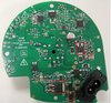
Refer to the center hole and the 2:00 clock position going from it to the 100 ufd C9 E-cap can. Go to its left to the gold flashed round test point labeled as PULSE.
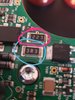
Then located just to its right, should be the vertical rectangular layout of the 4 terms of the OPTICAL INTERRUPTOR . Top two pins are th SENSE and the bottom two, are for the illuminating LED . . with it being .fed through SM R7.
If your unit will still power up from AC power measure the DC supply voltage across the minor gold two test points to see what that supply line voltage is .
Then past the R7 to see what the dropped volage is.
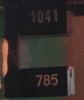
Also go on up to the very top to the large REG1 and pass us all of its numbers.

OMRON 1041 . . . . .
http://www.farnell.com/datasheets/1813202.pdf


hat shows it to be using an internal IR LED emitter with the same low Vf as does a visible Red LED and is using an ~ 20 ma current pull.

ASIDE:
Since you now DO have a disassembled unit, should you want to be my remote hands and eyes, I could give you more information on the whole unit.

73's de Edd . . . . .


People will believe almost anything . . . . . if you initially just cast furtive glances both ways and then go in and whisper it to them.

.
 

stefhelm

Jan 17, 2021
3
Joined
Jan 17, 2021
Messages
3
Thank you very much. Great information. I fortunately do have a friend to help me out with the assembly of the new parts as this stuff is not my strong suit.

As for how it all happened... I have no idea. I opened it all up as I heard the broken chunk of interrupter rattling around. Nothing is deformed other than the capacitors. They are raised significantly off the board and one is totally missing a connection (how the heck is a pin totally missing from under the capacitor??)
I'm assuming that them moving was the initial cause... bearings in the roller are solid, so the interrupt wheel should have never been off its its axis. The cylinder bodies of the capacitors look a little bashed up like one or two could have taken a hit. Soon as the interuppter broke, I'm sure that is what flew in to the optical unit and ripped it off. Strange series of events. It does still power up. I was able to do a firmware update prior to knowing what was wrong.

I think the is good possibility of getting up and running!
 

Calvincrampton

Jan 30, 2021
1
Joined
Jan 30, 2021
Messages
1
Hi all, just wanted to say a massive thanks for the information. My turbo blew the same as yours and with the aid of this thread I have been able to purchase the components, bludgeon them on with my rubbish £30 soldering gun from maplins and get it running again. I’ve never tackled anything like this before and the great advice on here enabled me to fix it. I thank you
 

waynegiles

Nov 5, 2021
1
Joined
Nov 5, 2021
Messages
1
Some info for anyone interested,
If you trace the circuit from the live mains terminal there is a 1amp fuse next is a 27 ohm 2 watt wire wound resistor, this is the one that blows apart next is a 3 ohm resistor and finally connected to that is a mosfet

RS numbers 6476188 27 ohm 3 watt
2240070 3 ohm 1 watt
7610689 n channel mosfet 650v 12amp
All in cost about a tenner from rs components. Mine now works. Might be best if you know someone that is experienced in electronics that has the correct soldering kit as the parts are pretty small

Thanks for your advise. Carried out the replacement and now all working.
 

jpmas

Jan 10, 2022
2
Joined
Jan 10, 2022
Messages
2
Hi all, sorry to revive an old thread, however, I’m trying to revive my t2240 trainer. I have replaced the two mosfets mentioned earlier in the thread and the two 3r3 resistors both test fine on the pcb, so I’ve left those in place. It appears that the resistor marked 223 (circled in red in attached photo) has failed. Does anyone have a link to a replacement? I’m struggling to track this resistor down and my resistor knowledge isn’t what it probably should be.

Thanks
 

Attachments

  • 43F9A8A3-659A-4D75-AFBB-93A52B8E2D22.jpeg
    43F9A8A3-659A-4D75-AFBB-93A52B8E2D22.jpeg
    161.6 KB · Views: 30

jpmas

Jan 10, 2022
2
Joined
Jan 10, 2022
Messages
2
Thanks for the info Bertus. Is this a thick film resistor or a thin film resistor? What wattage does it need to be?

All info is much appreciated, thank you!
 
Top