Maker Pro
Maker Pro

Soft start circuit

rajat

Jun 3, 2012
16
Joined
Jun 3, 2012
Messages
16
Dear All,
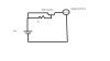
I am trying to make soft start circuit for halogen light using this circuit

http://i187.photobucket.com/albums/x312/sv_ted/softstart.jpg
reference: http://www.bikeforums.net/archive/index.php/t-357675.html

This is DC circuit with battery connected capacitor to p-mosfet which then connects to resistor and diode.

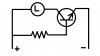
I am trying to replace p-mosfet with BC 547 NPN transistor.
Datasheet
http://datasheet.octopart.com/BC547-Fairchild-datasheet-7074.pdf

Can anyone advise me whether I can do this using the same circuit as shown in pic above or do i need to add more component for usinG NPN transistor safely.

I am assuming it is 12 v battery?

An advice greatly appreciated.
 

(*steve*)

¡sǝpodᴉʇuɐ ǝɥʇ ɹɐǝɥd
Moderator
Jan 21, 2010
25,510
Joined
Jan 21, 2010
Messages
25,510
If you're going to do it with a bipolar transistor, then you'd be best advised to use a 2N3055 (the BC548 is likely to expire in a puff of magic smoke)

With a 2N3055, connect a resistor from base to +ve, the emitter to -ve an the lamp between the collector and +ve.

The resistor should be calculated to be R = (V*15)/I where V is the supply voltage, I is the lamp current, and R is the resistor value in ohms.

For example if it's a 12V 5W lamp, I = 0.2, and so R = 900 ohms (1/2W is OK)

If it's a 60W 12V bulb... I = 5, and so R = 36 ohms (use 39 ohms) (and this needs to be a 10W resistor)

This circuit will supply a nearly constant current to the bulb. This will cause the bulb to start up slower, the speed depending on many factors, but typically the higher the wattage the slower it will heat up.

The transistor should have less than 0.5V across it once the bulb is fully on. (less is better). Reduce the value of the resistor to more fully saturate the transistor.

The resistor's wattage rating should be comfortably in excess of V^2/R (somewhere between 150% and 200% of this value is best. Larger is OK, but it will just be wasting money.)
 

rajat

Jun 3, 2012
16
Joined
Jun 3, 2012
Messages
16
Thank you Steve for your reply and brief explanation.

To go through steps slowly-please see diagram attached that shows resistor from base to +ve, the emitter to -ve an the lamp between the collector and +ve

Further I have only LM317T or BC 548 available with me.

Can I not use LM317T instead?

I am trying to soft start 50 W DC halogen bulb @ 12 V. Hence P =VI, i.e. I = 4.2 Amp

1) Selecting right transistor:
BC 547 - Based on datasheet
http://datasheet.octopart.com/BC547-Fairchild-datasheet-7074.pdf

My understanding that why BC 547 is not acceptable is because Ic (collector current)
is limited to 100 mA whilst required current can be as high as 4.2 amp. Please advise
if different.

2N3055- Based on datashhet
http://www.onsemi.com/pub_link/Collateral/2N3055-D.PDF
Collector current is 15 A dc - is this the reason why this is acceptable?

LM317T
Can I use LM317 T instead as this the only one available to me?
http://www.fairchildsemi.com/ds/LM/LM317.pdf


2. Resistor
R = (V*15)/I
In terms of Resistor calculator, why a safety factor of 15 is taken please advise?

Thanks for your time.
 

Attachments

  • Soft Start Circuit.png
    Soft Start Circuit.png
    10.5 KB · Views: 563

(*steve*)

¡sǝpodᴉʇuɐ ǝɥʇ ɹɐǝɥd
Moderator
Jan 21, 2010
25,510
Joined
Jan 21, 2010
Messages
25,510
Thank you Steve for your reply and brief explanation.

No problems

To go through steps slowly-please see diagram attached that shows resistor from base to +ve, the emitter to -ve an the lamp between the collector and +ve

Actually, your diagram is wrong. This is what I explained:

attachment.php


Further I have only LM317T or BC 548 available with me.

Neither will be acceptable.

Can I not use LM317T instead?

No. And for several reasons.

Firstly it is only capable of about 1 Amp.

Secondly (and most importantly) it would probably only supply about 9 volts to the lamp.

I am trying to soft start 50 W DC halogen bulb @ 12 V. Hence P =VI, i.e. I = 4.2 Amp

I am assuming that you understand what soft-start is with respect to a filament bulb, that is to reduce or eliminate the switch on current spike caused by the low resistance of the filament when it is cold.

1) Selecting right transistor:
BC 547 - Based on datasheet
http://datasheet.octopart.com/BC547-Fairchild-datasheet-7074.pdf

My understanding that why BC 547 is not acceptable is because Ic (collector current)
is limited to 100 mA whilst required current can be as high as 4.2 amp. Please advise
if different.

the Ic max is one thing, the other is the maximum power dissipation. But sure, once you look at the max collector current you wouldn't bother to look further.

2N3055- Based on datashhet
http://www.onsemi.com/pub_link/Collateral/2N3055-D.PDF
Collector current is 15 A dc - is this the reason why this is acceptable?

Yes. And it's a well known and easily obtainable power transistor which will be able to dissipate the heat that is caused by the voltage drop across it.

LM317T
Can I use LM317 T instead as this the only one available to me?
http://www.fairchildsemi.com/ds/LM/LM317.pdf

No. See reasons above. It's a bit like needing a boat and asking if a wheelbarrow would work. Different tool for a different purpose.

2. Resistor
R = (V*15)/I
In terms of Resistor calculator, why a safety factor of 15 is taken please advise?

That's not a safety factor, that's an estimate of the current gain of the transistor. If you look at the datasheet, you'll find that the gain varies significantly. It pays to pick a value near the low end. It also pays to check (as I suggested) the effect of this resistor as it may be worthwhile trimming the value to get a good compromise between the maximum current through the bulb during startup and the voltage across the transistor during operation.
 

Attachments

  • slow.png
    slow.png
    4.9 KB · Views: 1,307

KrisBlueNZ

Sadly passed away in 2015
Nov 28, 2011
8,393
Joined
Nov 28, 2011
Messages
8,393
Steve, did you intend to put a capacitor from the base to the emitter?
 

KrisBlueNZ

Sadly passed away in 2015
Nov 28, 2011
8,393
Joined
Nov 28, 2011
Messages
8,393
Here's a soft start circuit I designed yesterday. I wasn't going to post it, since it's not directly relevant to the OP's problem, but it might be of interest.

attachment.php


It takes a +12V supply and drives a 1.5A load. I've just used a resistor here; I guess it would have been better to simulate it with a lamp.

attachment.php


The graph above shows how the load current increases over a period of about 0.7 seconds from the time that the voltage source switches on (which is 0.1 seconds into the simulation).

attachment.php


The graph above shows three important circuit points: the voltage at point A (in green), the voltage at point B (in blue) and the current into Q3's base (in red).

C1 is initially discharged so point A jumps to +12V when the power source turns on. Q1's emitter is pulled up to +12V so Q1 doesn't conduct, and no current flows in Q2 and Q3. Q3's collector sits at 12V.

Point B is pulled to about 1.4V below Q3's collector voltage, so C1 starts to charge through R1. At around 0.17 seconds in the simulation, Q1 starts to conduct and causes current to flow in Q2 and Q3. Q1 now acts as a comparator, comparing the point A voltage against its emitter voltage, which is equal to Q3's collector voltage plus about 2V.

As the voltage at point A falls, the action of Q1, Q2 and Q3 causes Q3's collector voltage to fall in unison. At the same time, the voltage at point B follows Q3's collector voltage with a 1.4V drop, so the voltage across R1 remains fairly constant. This gives a relatively straight ramp-up of output current (see the first graph).

You can see Q3's base current increasing steadily - the red trace on the second graph. Around 0.77 seconds, the point A voltage is still dropping but Q3 reaches saturation (the load current tops out at about 1.47A and there is about 0.23V on Q3's collector). Q3's base current rises rapidly and eventually tops out at about 90 mA; this is limited by R4.

D1 ensures that C1 discharges when power is removed and protects Q1 from reverse base-emitter voltage.

I don't think this design is very suitable for the OP's application. I would use a MOSFET instead of a transistor; this circuit wastes about 6% of its total operating current in base current for the 2N3055! I thought it might be interesting to other forum folks.
 

Attachments

  • soft start idea.gif
    soft start idea.gif
    5.9 KB · Views: 2,808
  • soft start load current.gif
    soft start load current.gif
    5.2 KB · Views: 1,321
  • soft start other circuit points.gif
    soft start other circuit points.gif
    7.1 KB · Views: 1,118

(*steve*)

¡sǝpodᴉʇuɐ ǝɥʇ ɹɐǝɥd
Moderator
Jan 21, 2010
25,510
Joined
Jan 21, 2010
Messages
25,510
Steve, did you intend to put a capacitor from the base to the emitter?

No. It's essentially a very quick and dirty constant current source (or in this case.. sink).

The base resistor sets the base current and therefore the maximum collector current.

If you wanted efficient, you'd be using a LED. ;)
 
Top