osterchrisi
- Mar 8, 2011
- 28
- Joined
- Mar 8, 2011
- Messages
- 28
Hi!
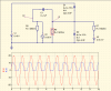
I have a question concerning input protection: Say, I have a circuit that is running on a 9V battery and so are the opamps used in this circuit of course. The input signal is is ac coupled and shifted to float around 4.5V.
If I want to protect the chips from being damaged I was thinking about putting clamping diodes before the first signal processing opamp, so as to limit any incoming signal to max. 9Vpp. But what to do with the two diode drops on each side of the power rails? Because obviously the signal is then going between -0.6V and +9.6V which I think is out of most common mode voltage ranges of opamps, no?
Can you give a hint at how to protect the input of a circuit safe?
I attached a simulation for better understanding...
Thanks a lot for any advice!!!