Maker Pro
Maker Pro

Selenium rectifier?

TCSC47

Mar 7, 2016
148
Joined
Mar 7, 2016
Messages
148
Hi Everybody
I have been trying to find the data sheet and any details available of what I believe to be a selenium bridge rectifier. The component came out of a model train controller I bought way back in 1962 (How time flies!!) here in the UK. The controller was made by Hammant and Morgan who are no longer around, but collectable amongst some model train enthusiasts.

I have replaced the rectifier with a semiconductor bridge rectifier because, at 60 yrs old, I would not want the selenium rectifier to break down emitting toxic fumes. Works fine after adding a 10K resistor across the + - terminals.

I have to admit that I don't really need the info but I am just somewhat irritated as to why I have been so unsuccessful in finding the data on the internet.

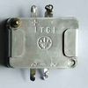
The picture I have attached shows the component and a rough sketch of the small signal characteristics of one of the selenium diodes. The selenium bridge has LT61 impressed into it. The logo looks like a trident with a horizontal line across it. I can not find anything relevant pertaining to either the number or the logo.

Any comments appreciated. Cheers, all.
 

Attachments

  • IMG_20231107_120025.jpg
    IMG_20231107_120025.jpg
    360.8 KB · Views: 28
Last edited:

Minder

Apr 24, 2015
3,478
Joined
Apr 24, 2015
Messages
3,478
Why do you show the bridge with two -ve terminals?
The original apears to have the standard four?
2 for AC and -ve and +ve?
You shouldn't need a resistor?
 

kellys_eye

Jun 25, 2010
6,514
Joined
Jun 25, 2010
Messages
6,514
I have to admit that I don't really need the info but I am just somewhat irritated as to why I have been so unsuccessful in finding the data on the internet.
Given its age and unsuitability for modern use the only way the datasheet might be available would be if an enthusiast scanned the original and put it up somewhere. It's actually likely to be the case but unless it has been 'tagged' appropriately you won't find it easily by regular search methods.

here's a link to a selenium rectifier catalog as an example:


Bluejets

Oct 5, 2014
6,981
Joined
Oct 5, 2014
Messages
6,981
Any comments appreciated
It is much easier to follow the circuit of a full bridge rectifier if it is drawn in the common accepted way of a diamond with the two AC top and bototom and the negative on the left with all arrows (diodes) facing the postiive terminal.
And again, no need for the resistor you mentioned, possibly a smoothing electrolytic capacitor across the output, approx 1000uF per amp.
 

Attachments

  • FullBridge.jpg
    FullBridge.jpg
    14.3 KB · Views: 5

TCSC47

Mar 7, 2016
148
Joined
Mar 7, 2016
Messages
148
Why do you show the bridge with two -ve terminals?
The original apears to have the standard four?
2 for AC and -ve and +ve?
You shouldn't need a resistor?
It is not too obvious from my picture, but enlarge the picture of the component and look carefully at the -ve tabs. I haven't pictured it from the best angle but you should be able to see one tab behind the other one. The two -ve terminals are an interesting point. The function they serve in the train controller is to allow switching between full wave rectification and half wave rectification. This feature was intended to to give a "rougher" output that would help drive "sticky" motors and overcome friction of the locomotives. This was the 1950's and small electric motors and mechanisms were no way as smoothly functioning as present day models. I have always thought it was only a bit of a gimmick.

Incidentally, I have found a similar set up in my car battery charger to switch between high and low charge rates.

As for needing a resistor across the output, I found that with no load on the supply, my DVM connected to the output showed a build up of charge to provide a reading of 80 V or so. I assumed that the leaky nature of the selenium rectifier obviated the need for a resistor.
 

TCSC47

Mar 7, 2016
148
Joined
Mar 7, 2016
Messages
148
It is much easier to follow the circuit of a full bridge rectifier if it is drawn in the common accepted way of a diamond with the two AC top and bototom and the negative on the left with all arrows (diodes) facing the postiive terminal.
.Is it?
And again, no need for the resistor you mentioned,
See my comment on the resistor above.

possibly a smoothing electrolytic capacitor across the output, approx 1000uF per amp.
The controller was designed for model train control in he 1950's and way back then a 1000uF cap would have been rather bulky and in any case unnecessary for the application. The proof of the pudding is that it operates both my modern and my vintage locos smoothly enough.
 

Delta Prime

Jul 29, 2020
2,033
Joined
Jul 29, 2020
Messages
2,033
I have to admit that I don't really need the info but I am just somewhat irritated as to why I have been so unsuccessful in finding the data on the internet
The controller was made by Hammant and Morgan who are no longer around, but collectable amongst some model train enthusiasts
Bingo! Try old model train enthusiast websites someone had to post something pertaining to your query.
;)
Any comments appreciated
I'm only saying this because you didn't really need the info on you're switchable full/ half wave selenium rectifier bridge.
i bet you tell killer bedtime stories!
I loved your explanations.
But you left me yearning for more... Your model train what was it?all the info. What gauge? and did it have smoke coming out the top? all that stuff. Did it have a whistle? A cattle catcher?
Was your railroad track going up a steep hill that you had to switch it from full wave to half wave?
What was the cargo? Livestock, people.
And most importantly.
Did it have a caboose?
:)
 

Bluejets

Oct 5, 2014
6,981
Joined
Oct 5, 2014
Messages
6,981
Any comments appreciated.

So I did....then you argue the point.

If you know all about it why ask in the first place.

BTW...pwm has overcome most of the problems you present.

If you want to switch half and full wave as per original, simply use 4 separate diodes.

Note that schottky diodes will give a lower voltage drop.
 

TCSC47

Mar 7, 2016
148
Joined
Mar 7, 2016
Messages
148
So I did....then you argue the point.

If you know all about it why ask in the first place.

BTW...pwm has overcome most of the problems you present.

If you want to switch half and full wave as per original, simply use 4 separate diodes.

Note that schottky diodes will give a lower voltage drop.
Apologies, I did not mean to sound argumentative. I was commenting on the 1950's design as I found it. Your comments are quite valid and pretty much the same as the ones I pondered upon. I think the answers are mainly that the design was governed by 1950's available technology. A modern train controller would be quite different, as you point out.

Thanks for your response.
 
Last edited:

TCSC47

Mar 7, 2016
148
Joined
Mar 7, 2016
Messages
148
Bingo! Try old model train enthusiast websites someone had to post something pertaining to your query.
;)

I'm only saying this because you didn't really need the info on you're switchable full/ half wave selenium rectifier bridge.
i bet you tell killer bedtime stories!
I loved your explanations.
But you left me yearning for more... Your model train what was it?all the info. What gauge? and did it have smoke coming out the top? all that stuff. Did it have a whistle? A cattle catcher?
Was your railroad track going up a steep hill that you had to switch it from full wave to half wave?
What was the cargo? Livestock, people.
And most importantly.
Did it have a caboose?
:)
Cheers. There is a lot written on Hammant and Morgan controllers available from the 1950's to 1970's in the UK model train forums and blogs, mainly I think because of nostalgia. The fact that so many are still around speaks to their toughness and uniqueness. I haven't yet found anything about the origin of the selenium rectifiers though, but I will have another look.

There is much that can be written about them that I think might be interesting to people here, but I think this would take the string out of the relevance of this component identification section of the forum. Would it be possible for this string to be moved to a more relevant section if I open up the string to talking about the controllers in general? Or perhaps I will just start a new thread in the appropriate area.
 
Last edited:

Harald Kapp

Moderator
Moderator
Nov 17, 2011
13,758
Joined
Nov 17, 2011
Messages
13,758
I have always thought it was only a bit of a gimmick.
Incidentally the use of a half bridge rectifier has the same effect here as using pwm to control DC motors at low speed: the high peak voltage helps to overcome friction and inertia, while the pulsed waveform results in an overall lower voltage and consequently in lower speed.
 

TCSC47

Mar 7, 2016
148
Joined
Mar 7, 2016
Messages
148
I think I have just realised why there are two negative pins. It is due to the way the selenium rectifier is manufactured as layers forming four diodes. There will always be two diodes on the outside that have to connect to each other hence the two -ve have to link up over the outside. Normally the two -ve are linked to form a complete bridge but in the case of my train controller, switching out the link provides the function of switching from full wave rectification to half wave.
 

TCSC47

Mar 7, 2016
148
Joined
Mar 7, 2016
Messages
148
Incidentally the use of a half bridge rectifier has the same effect here as using pwm to control DC motors at low speed: the high peak voltage helps to overcome friction and inertia, while the pulsed waveform results in an overall lower voltage and consequently in lower speed.
I hadn't thought of that.
 

Delta Prime

Jul 29, 2020
2,033
Joined
Jul 29, 2020
Messages
2,033
I haven't yet found anything about the origin of the selenium rectifiers though
but I think this would take the string out of the relevance of this component identification section of the forum.
That says to me... You're train did not have a caboose!


Screenshot_20231108_213308.jpg
 

Attachments

  • americanplatingpower.pdf
    255.9 KB · Views: 4
  • srhbst.pdf
    4.4 MB · Views: 5
Last edited:

TCSC47

Mar 7, 2016
148
Joined
Mar 7, 2016
Messages
148
Thanks for these publications DP.
Re - lack of caboose. As you no doubt know, present day trains don't have cabooses. As I am a lad from the 50's this always looks WRONG to me so if I could make a law, it would be that all freight trains must have a caboose, even if they are not needed.
 

Delta Prime

Jul 29, 2020
2,033
Joined
Jul 29, 2020
Messages
2,033
if I could make a law, it would be that all freight trains must have a caboose, even if they are not needed.
I thought I was the only one.
The owner has to paint the caboose red or he will be thrown underneath his own train.
 

TCSC47

Mar 7, 2016
148
Joined
Mar 7, 2016
Messages
148
Did a Google image search on your part, will let you wade thru results :

View attachment 62270


Regards, Dana.
Thanks Dana. These mirror the results that I have been getting. This selenium rectifier does simply just not seem to exist on the internet. How many things out there do not? That is why it sparked my interest in it and I thought it might be an interesting thing for the forum to chew over.
Anyway thanks to everybody (including the ones I upset, which I don't understand). I now know quite a bit more about selenium rectifiers.
 
Top