Maker Pro
Maker Pro

Rotel RA820A stereo amp no right channel

juz571

Oct 8, 2023
20
Joined
Oct 8, 2023
Messages
20
Hi,
I am looking for some guidance, if possible? I am an electrician of 30 years, but my electronics knowledge is at a foundation level, lets say!

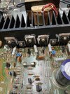
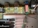
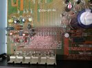
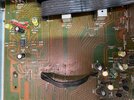
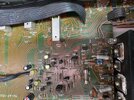
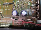
So I bought this nice old amp from Ebay and it was sold as only 1 channel working. I opened it up and had a quick inspection. Nothing obviously damaged, to the eye, so I started checking fuses. Fuse F601 was popped (schematics attached), so I replaced it and, bingo, we had 2 channels again.
So today I put the lid back on and give it another check. Only 1 channel again. But the fuse has not blown this time. What is puzzling is, that fuse F601 does the left channel, but it's now the right channel that's gone down! (F602 is fine). I've tried with multiple inputs and checked both speaker outputs as well as headphones and there's no right channel on anything

Thanks in advance and any help will be greatly appreciated
 

Attachments

  • Rotel-RA-820A-Service-Manual.pdf
    3.8 MB · Views: 1

kellys_eye

Jun 25, 2010
6,514
Joined
Jun 25, 2010
Messages
6,514
Did you use the correct rated fuse? 4A is not exactly common and replacing it with something larger is a no-no.

What are F901 and F902 like? I'd check for distorted smoothing capacitors first (visual checks first) then we can start doing some basic test measurements assuming you have a test meter?
 

juz571

Oct 8, 2023
20
Joined
Oct 8, 2023
Messages
20
Did you use the correct rated fuse? 4A is not exactly common and replacing it with something larger is a no-no.

What are F901 and F902 like? I'd check for distorted smoothing capacitors first (visual checks first) then we can start doing some basic test measurements assuming you have a test meter?
Thanks for the reply Kellys_eye. Ummmm......no, I didn't use a 4A as I didn't have one (embarrassed face). I must confess I used a 6A. I know, I'm a fool! The thing is it's the right hand channel that's gone now. F601 does the left channel if I'm reading the schematic right? All fuses are fine at the moment. Yes I have various test meters and an oscilloscope, but no esr meter at present. No obvious signs of any bad caps from what I can see. I've got some 4A fuses coming tomorrow to get that right before I go any further.
 

kellys_eye

Jun 25, 2010
6,514
Joined
Jun 25, 2010
Messages
6,514
get that right before I go any further.
Too late!

Usual issues, apart from capacitor ESR, would be a short in one of the amplifier output transistors but we must establish that the sections are receiving the right voltages and that there's no bad ripple (as a dud capacitor would introduce).

Sure you didn't inadvertently cross the speaker connections after fitting the new fuse? i.e. mistaking the left/right channels.
 

juz571

Oct 8, 2023
20
Joined
Oct 8, 2023
Messages
20
Too late!

Usual issues, apart from capacitor ESR, would be a short in one of the amplifier output transistors but we must establish that the sections are receiving the right voltages and that there's no bad ripple (as a dud capacitor would introduce).

Sure you didn't inadvertently cross the speaker connections after fitting the new fuse? i.e. mistaking the left/right channels.
Definitely no crossing of the speakers. I double checked after my last reply. Was 100% the fuse for the left channel that was blown when I got it, and now it's the right channel that has failed. I've checked with speakers in both outputs (main and remote) and on headphones. I turn the balance to the right and there is nothing at all. Not even a faint sound as far as I can tell.
 

juz571

Oct 8, 2023
20
Joined
Oct 8, 2023
Messages
20
6 amp fuse in a 4 amp slot?
Take some photos sparky. I got to see this. :)
Ok, ok. I get it! We’re not so delicate as you electronics guys! Use what’s at hand and see if it pops again! Photos attached. Hope they are clear enough. The 6A is the white fuse btw
 

Attachments

  • IMG_1858.jpeg
    IMG_1858.jpeg
    470 KB · Views: 14
  • IMG_1857.jpeg
    IMG_1857.jpeg
    334.8 KB · Views: 14
  • IMG_1856.jpeg
    IMG_1856.jpeg
    425.4 KB · Views: 14
  • IMG_1855.jpeg
    IMG_1855.jpeg
    436.3 KB · Views: 13
  • IMG_1854.jpeg
    IMG_1854.jpeg
    491.2 KB · Views: 13
  • IMG_1853.jpeg
    IMG_1853.jpeg
    382.1 KB · Views: 14

Delta Prime

Jul 29, 2020
2,006
Joined
Jul 29, 2020
Messages
2,006
Just in time for Halloween what a horror story you got to clean all that up with isopropyl 99.9% alcohol. Do not power that unit back up again.
 

Martaine2005

May 12, 2015
4,956
Joined
May 12, 2015
Messages
4,956
Below F601, there’s a resistor. The track looks ‘scraped’ away rather than a blown track. Have you been scraping?.
Also, 30 years sparky? Puts a 6A in a 4A?. To see if it ‘pops’. Electronics is not like a consumer unit.
Ohms law tells you that another 3rd current will be present. Let alone the overheads.
Anyway, the component is open circuit or you’d be blowing the fuse again.
 

Martaine2005

May 12, 2015
4,956
Joined
May 12, 2015
Messages
4,956
Also, just viewing the other photos, there are many points that look like the traces have been scraped away.
I’d definitely clean the boards first with IPA (as suggested) and then check the scraped or broken traces before another power check.

Martin
 

juz571

Oct 8, 2023
20
Joined
Oct 8, 2023
Messages
20
Below F601, there’s a resistor. The track looks ‘scraped’ away rather than a blown track. Have you been scraping?.
Also, 30 years sparky? Puts a 6A in a 4A?. To see if it ‘pops’. Electronics is not like a consumer unit.
Ohms law tells you that another 3rd current will be present. Let alone the overheads.
Anyway, the component is open circuit or you’d be blowing the fuse again.
Hi Martin, no I’ve not done any scraping. I see what you mean about the track though, It doesn’t look good at all. Believe it or not I’ve already given a clean with cotton buds and isopropyl before I took these photos. That’s how bad it was before!
 

Delta Prime

Jul 29, 2020
2,006
Joined
Jul 29, 2020
Messages
2,006
Believe it or not I’ve already given a clean with cotton buds and isopropyl before I took these photos
I believe you; but you must know... I am a masochist; show me the solder side of the board.
And I will see if we cannot cure your insanity. :D
 

kellys_eye

Jun 25, 2010
6,514
Joined
Jun 25, 2010
Messages
6,514
That's not the track, that's just the topside print to assist with following the circuit layout - the tracks are under the board.
 

kellys_eye

Jun 25, 2010
6,514
Joined
Jun 25, 2010
Messages
6,514
Check the +37 and -37V rails then measure at either end of F601 and F602, report all you find.
 

Delta Prime

Jul 29, 2020
2,006
Joined
Jul 29, 2020
Messages
2,006
And I'm telling you do not power that unit up! Just take the photos. Solder side please...
 

Delta Prime

Jul 29, 2020
2,006
Joined
Jul 29, 2020
Messages
2,006
There's no risk. The damage has been done. This isn't CMOS stuff so the risk of other faults happening are minimal.
Do not presume to tell me what risks are involved. :mad:
Go ahead take the advice of an old fart; your words not mine.
Just playing; yeah,what the hell, I admit it you are my Superior; let's see what kind of voltage you have on your rails?
 

juz571

Oct 8, 2023
20
Joined
Oct 8, 2023
Messages
20
OK I'll take some readings when I get home tonight. Thanks all for your assistance on this. I really do appreciate you guys taking time out of your days to help. And I promise I'll never put a oversized fuse in again!
 
Top