Maker Pro
Maker Pro

Repair RF amplifier board

otpisani

Aug 31, 2023
16
Joined
Aug 31, 2023
Messages
16
Please can you clarify something for me, because I don't have that strong power supply to offer right now, can offer 53V and up to 5A. can I configure bias voltage/current settings for gate or not, not to run amplifier like in production stage, so that I forget that story for now, until I buy stronger supply or not.

The bias setting voltage (anywhere from 0-10V) must also be available for the whole span. There is no way to guess how high or low this bias voltage needs to be so unless you have it ALL available you might never get it set.
10V is max. voltage for MRF300AN/BN gate side, mosfets will get burned or not, anyway voltage regulator WS78M05A2218 is configure for output of 5V no matter how much offer on input side just for that purpose, or I don't understand you correctly.
 

bertus

Moderator
Nov 8, 2019
3,350
Joined
Nov 8, 2019
Messages
3,350
Hello,

On the board is written "2.7 volts or 300 mA" for the bias.
The 5 Volts from the regulator are more than enough.

Bertus
 

bertus

Moderator
Nov 8, 2019
3,350
Joined
Nov 8, 2019
Messages
3,350
Hello,

I was wrong with the statement that the transistors are the same.
The AN and BN versions are mirrored:
MRF300AN_BN_RF_IMG_TO-247-3L.jpg
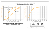
Also the 2.7 Volts can be seen in the graph in the datasheet:
MRF300_gate voltage vs power.png
Bertus
 

Attachments

  • MRF300AN.pdf
    1.3 MB · Views: 1

otpisani

Aug 31, 2023
16
Joined
Aug 31, 2023
Messages
16
I can confirm that removing thermal pads achieve something, now I have continuity between left side ground (53V) and drain, and right side (12V) and drain, before removing pads I only have continuity between both sides and gate, presume that is resistance but it's the same in the value on the both side, as it should be around 1900, and for gate side continuity values depends from that blue trimmer, which is also correct, know that because have amplifier with worse features.
Removing pads didn't change anything about suddenly drops of voltage from 53V to 12-8-6, and that happened always when I set trimmer on both side around 2.2-2.3V

Before de soldering mosfets plan to move step voltage regulator and put 12V power supply for gate side, if any one have some idea before de soldering mosfets....
 

bertus

Moderator
Nov 8, 2019
3,350
Joined
Nov 8, 2019
Messages
3,350
Hello,

The backside of the transistors is connected to the source of the transistors.
See the first page of the datasheet for more info.

Bertus
 

otpisani

Aug 31, 2023
16
Joined
Aug 31, 2023
Messages
16
Means, maybe everything is in bad grounding, I will need to look this page again what author made
 

kellys_eye

Jun 25, 2010
6,514
Joined
Jun 25, 2010
Messages
6,514
It's not possible to 'guess'
I will need to look this page again what author made
That article covers just about everything you need to know. It also shows how substantial your heatsink needs to be and how the author managed to correctly mount the devices to the heatsink to ensure safe operation.

Please read the article and try to understand what is in it. With RF devices such as this amplifier you can't just 'fumble through' and expect it to work.
 

otpisani

Aug 31, 2023
16
Joined
Aug 31, 2023
Messages
16
Do I need to close this tread, and after I get missing parts open new one if I stumble again :) or not, need to order thermal paste, build proper radiator, etc
 

otpisani

Aug 31, 2023
16
Joined
Aug 31, 2023
Messages
16
I read article, actually he made 3 version based on the MR300AN/BN, he also get some reward from NXP for building that amp, in article that I also share previous link, he mention that this kind of mosfets are usually soldered directly on chassis, but not this one, which need thermal paste, but he suggest liquid metal, also he put mosfets on copper, which is actually in sandwich between Al radiator and amp board. In second article, which is actually PDF instructions file for he's DIY amp board, he actually saying that trimmer on board, but without mosfets., need to be turned until 2.2V on gate side, and after that you need to mount mosfets, and configure current on both side up to 200mA.

In my case "party" also starts around 2.2V, when amp board suddenly losing voltage and current goes up. In the meanwhile I just clean surface from Al chassis, but because I don't have liquid paste, have some artic thermal paste for PC CPU, but conductivity is not even close with thermal paste that he used (Thermal Grizzly Conductonaut), but you actually need el. conductivity, not thermal conductivity, which Thermal Grizzly Conductonaut doing just fine (it's actually doing both purpose)

Also I de-solder mosfets, and test them with multi meter, seems to be ok, I'm in the processes to purchase bigger Al radiator, need to by that liquid paste, and plan to buy also 10x10 copper sheet plate.

So that 2.2V actually can't be coincidence, presume that would be that "magic" with treshold voltage from source to drain. Mine question would be, because I never seen that before, when you turning trimmers in that "treshold phase", voltage need to be the same, but only current need to go up slowly, until you reach let say 200mA, per side, but in my case because chassis with back side surface of mosfets in contact, can't provide actually, that good el. conductivity, voltage drops, and resistance goes wild. Can someone comment that, please.
 

otpisani

Aug 31, 2023
16
Joined
Aug 31, 2023
Messages
16
I would like to re post old thread, now amp is build as it should,

Issue is that signal don't boost at all, I have one power supply, for drain and gate. On gate side I have voltage down converter, and can confirm that voltage converter can supply actually around 12-14V 1.5A under working condition, because I try with some cheap amp operating around12-14V, and voltage converter starts acting funny around 1.5-1-6A. From manual gate side needs around 1A and 12V.

I actually don't have proper power supply on drain side, it's some cheap Chinese Voltage/current adjustable power supply, but can provide only 4A at 53V, and manual says 15A and 53V, don't know if fet needs that much current when actually starts, although MRF300AN and MRF300BN are not toy gadgets.

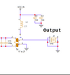
Manufacturer didn't provide any manual/debug manual, I don't know how to connect output coaxial cable, now is only central wire connected, usually ground and plus are connected on second magnetic coil (before output SMA, like on picture).
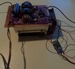
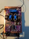
output_magnetic_coil.pngIMG_20240108_154019_088.jpgIMG_20240108_154104_056_1(1).jpg

What else can be problem why I don't have any boost signal on output SMA, think that mosfets are in good condition!!!???
 

kellys_eye

Jun 25, 2010
6,514
Joined
Jun 25, 2010
Messages
6,514
Are all the inductors correctly wound? The direction of the windings is critical. Get any one wrong and it won't work.
 

kellys_eye

Jun 25, 2010
6,514
Joined
Jun 25, 2010
Messages
6,514
In my case "party" also starts around 2.2V, when amp board suddenly losing voltage and current goes up.
This may indicate that your PSU can't deliver the required current.

Can you post the actual manuals you have on that unit?
 
Top