Maker Pro
Maker Pro

Repair RF amplifier board

otpisani

Aug 31, 2023
16
Joined
Aug 31, 2023
Messages
16
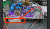
I need to repair this RF amplifier, although it never work, it's cheap one, and you don't have any schematic at all, and take care for heat dissipation, you need to buy MRF300An and MRF300BN mosfets, which I did but when everything connected, and board need two power supply one for drain and one for gate side, so I put voltage regulator on power supply for drain side, which need 53V, and downgrade voltage around 10.5V for gate side, but when is everything connected I don't have any current flowing!!!???,

I Can't regulated voltage with trimmer more than 2.2V on both side, and on amplifier board says that bias voltage need to be 2.7V or 0.3A. When I turn voltage around 2.3V on both side, than starts sudden drops in voltage on power supply, and current jumps around, but I regulated (blocked) with power supply max of 0.5A to let on amplifier board, just because that mosfets don't burn, so breaking point for both mosfets are around 2.3V, but again both side AN and BN are connected, you can't regulated with trimmer slowly current, although this trimmer are for fine step by step regulation.

Strange is also that I can continuity (diode mode) from ground to gate side, but I don't have continuity from ground to drain side.

Mosfets are new, and like to determine where is issue if someone can help
 

Attachments

  • IMG_20230825_092417_104.jpg
    IMG_20230825_092417_104.jpg
    282 KB · Views: 6

Delta Prime

Jul 29, 2020
2,038
Joined
Jul 29, 2020
Messages
2,038
What we have here is a failure to communicate! Something is being Lost in translation. I cannot follow your explanation…I cannot help you.
 

otpisani

Aug 31, 2023
16
Joined
Aug 31, 2023
Messages
16
Sorry, I bought cheap RF amp on ebay, but it's just board, you need to buy mosfets for board, MRF300AN and MRFBN, what I get from supplier as description are here:

600W 1.8-30MHz HF Power Amplifier HF RF Amplifier Board SSB HF Amp Board for Shortwave Radio DIY

Features:

- Frequency: 1.8-30MHz
- Input power: 1-5W
- Maximum output power: 600W
- Voltage: 12V+53V
- Current: 12V (1A); 53V (15A)
- Static voltage: 2.7V
- Quiescent current: 300mA+300mA
- Net weight: 276G/0.6LB
- Board size: 138 x 88 x 40mm/5.4 x 3.5 x 1.6" (LxWxH)

Package Included:
- 1 x HF Power Amplifier

Note:
- Transistors and heat sink are not included. Please purchase separately.
- Transistors, MRF300AN and MRF300BN, are recommended.


Instead that I attach another power supply for 12V, I put voltage regulator to supply gate side, but when everything connected and power on, i can regulate voltage on gate side with trimmer up to 2.7V, although you have label on amp board that bias gate voltage or current need to be 2.7V or 0.3A, when I turn voltage around 2.3V, power supply on which is LCD with voltage and current suddenly drop voltage from 53 arouns 12V, and current arround 0.4A, something is wrong, and trimmer is for fine tuning, don't know what you need more
 

Delta Prime

Jul 29, 2020
2,038
Joined
Jul 29, 2020
Messages
2,038
voltage and current suddenly drop voltage from 53 arouns 12V, and current arround 0.4A, something is wrong, and trimmer is for fine tuning, don't know what you need more
You're the one asking questions .
So you're a ham your Dxing 20 meter BAND ,14 MHz you're just following the instructions from the person who sold you a non-functioning RF board, there's one born every minute. Show me some photos of your RF board. If possible. Please, thank you.
 

otpisani

Aug 31, 2023
16
Joined
Aug 31, 2023
Messages
16
Voltage regulator is this one , but the same is also when I put power supply 12V, everything is new, and main power supply running drain side (53V) I blocked current up to 0.8A, that I'm sure that mosfet will not be burned when configuring them, although I suspect that something already burned ;-)
 

Attachments

  • IMG_20230831_202919_063.jpg
    IMG_20230831_202919_063.jpg
    350.8 KB · Views: 10
  • IMG_20230831_202929_187.jpg
    IMG_20230831_202929_187.jpg
    387.3 KB · Views: 10

bertus

Moderator
Nov 8, 2019
3,351
Joined
Nov 8, 2019
Messages
3,351
Hello,

The two transistors will be the same as the circuit seems to be balanced.
To adjust the bias of the transistors, I see two potentiometeters for setting the bias.

Is there a schematic available?

Bertus
 

otpisani

Aug 31, 2023
16
Joined
Aug 31, 2023
Messages
16
Nop, that would be issue, I tried already couple of times, but excuses are that he need to ask manufacturer, so that would be noise in communication!!!???

Yes, this trimmer are not rounded and imprecise, but predicted for fine tuning, and can't be that suddenly voltage drops from 53 to 12-14V, because blue trimmer lost main purpose.
I have continuity (diode mode) between ground and gate on both side, but don't have from ground to drain, already have some cheap amplifier and it's must, also don't have continuity between ground and +, where is power supply predicted on the board.

Don't know what to do, desolder mosfets down and check them with multi meter, something else....
 

bertus

Moderator
Nov 8, 2019
3,351
Joined
Nov 8, 2019
Messages
3,351
Hello,

Did the board come with instructions how to adjust the potentiometers?
With a wrong setting of the potmeters, you can burn the transistors.

Bertus
 

otpisani

Aug 31, 2023
16
Joined
Aug 31, 2023
Messages
16
They told you that you don't need to adjust anything, that is already done at manufacturer, but issue starts immediately when I put NXP new mosfets (suddenly voltage drops), what could I do wrong, burn them with high temperature, and they are predicted for such role, don't know.

I found this on net, and mine is presume similar, they took schematic change something on board, and put new version name and logo
 

bertus

Moderator
Nov 8, 2019
3,351
Joined
Nov 8, 2019
Messages
3,351
Hello,

Did you read this on that page:
The idle current for the MRF300 LDMOS transistors is set at 300mA each, with a bias gate voltage of around 2.7V. To achieve this value, a LM317HV high voltage linear regulator takes the supply voltage and adjusts it down to a value around 8-10V, which is further divided down to the exact value via individual adjustable multi-turn potentiometers.

Bertus
 

otpisani

Aug 31, 2023
16
Joined
Aug 31, 2023
Messages
16
I didn't run into that article before, but I read mosfet datasheet, and for gate side max is 10V, but sure I didn't set voltage regulator more than, think 10.5-11V, because board has voltage controller which can't bare more than 13V, although truth is that mine voltage regulator is not high quality voltage regulator, but he is doing role as it should. Manufacturer 78M05 translate mine 10.5 as input voltage to 5V for output voltage on board, not 8-10V as article says.

You are suggesting that I gave more voltage to that internal voltage regulator, which is WS78M05A2218....
 

bertus

Moderator
Nov 8, 2019
3,351
Joined
Nov 8, 2019
Messages
3,351
Hello,

In the RF amplifier they put the transistors in linear mode.
The page tells you that it happens at a gate voltage of about 2.7 Volts.

Bertus
 

otpisani

Aug 31, 2023
16
Joined
Aug 31, 2023
Messages
16
Can you just comment me this please, I put under mosfet thermal pad (it's not electro....), mosfets have big area under for cooling, but also for grounding, can this cause that!!!???

I will for that before, and thanks;

Robin
 

Delta Prime

Jul 29, 2020
2,038
Joined
Jul 29, 2020
Messages
2,038
You may be in luck.
Could you possibly take a clear photo of the assist tag , on your unit, & any other information that is on the board itself thank you.
photo_1693530722310.png
 

kellys_eye

Jun 25, 2010
6,514
Joined
Jun 25, 2010
Messages
6,514
There are many videos on Youtube that show the construction of 70W RF amplifiers that use the exact same principles except on a smaller scale.

Your 600W amplifier uses bigger transistors, larger ferrites and more volts/current but the operating principles (bias settings etc) and even the schematic are exactly the same. Setting the bias voltage is CRITICAL to proper operation and if you get it wrong you end up with a nasty expense. Your heatsink - for starters - is WAAAAYYYYY too small.

Where you may fail - spectacularly - is due to the higher voltages and currents used and the ease at which the RF devices can be destroyed by mis-adjustment and, IIRC the MRF300 devices aren't cheap and many sources - particularly via China/Ebay - are potential fakes.

Such RF amplifier boards were never made for those who don't have the necessary experience/skills. Are you aware of the very high voltages such units can deliver when resonating?
 

otpisani

Aug 31, 2023
16
Joined
Aug 31, 2023
Messages
16
No, that was mine old radiator from some PC, you only get purple board, but they put something there
 

Attachments

  • IMG_20230901_102029_457.jpg
    IMG_20230901_102029_457.jpg
    539.1 KB · Views: 3

otpisani

Aug 31, 2023
16
Joined
Aug 31, 2023
Messages
16
There are many videos on Youtube that show the construction of 70W RF amplifiers that use the exact same principles except on a smaller scale.

Your 600W amplifier uses bigger transistors, larger ferrites and more volts/current but the operating principles (bias settings etc) and even the schematic are exactly the same. Setting the bias voltage is CRITICAL to proper operation and if you get it wrong you end up with a nasty expense. Your heatsink - for starters - is WAAAAYYYYY too small.
Agree

Where you may fail - spectacularly - is due to the higher voltages and currents used and the ease at which the RF devices can be destroyed by mis-adjustment and, IIRC the MRF300 devices aren't cheap and many sources - particularly via China/Ebay - are potential fakes.
Mosfets are original from Mouser, board was purchased on Ali, yes just because mosfets are 46€ each I limited current on power supply up to 0.8A (0.3x2 for bias current +0.2A excess), that I have some protection when I configure bias gate, because of that I wonder if this could be issue

other data:
power supply 50-53V (0.8A), with voltage step regulator downgrade for gate bias voltage 10.5V

Such RF amplifier boards were never made for those who don't have the necessary experience/skills. Are you aware of the very high voltages such units can deliver when resonating?
 

otpisani

Aug 31, 2023
16
Joined
Aug 31, 2023
Messages
16
Not sure, for gate side there is on board voltage regulator (WS78M05A2218), who downgrade voltage from step voltage regulator 10.5V to around 5V. Although I couldn't find datasheet for that regulator, presume that belongs to LM7805 family, and datasheet for 78M05 says that max current output is 1A, although, think that I find some specs even 1.5A, more than enough for 600mA bias current (both mosfets side).
But I ask question if 0.8A is not enough, because sure left side (drain) and right side (gate) made one whole unit, because I don't have experinece with amplifiers I ask.
 

kellys_eye

Jun 25, 2010
6,514
Joined
Jun 25, 2010
Messages
6,514
The bias setting voltage (anywhere from 0-10V) must also be available for the whole span. There is no way to guess how high or low this bias voltage needs to be so unless you have it ALL available you might never get it set.
 
Last edited:
Top