Maker Pro
Maker Pro

Question on power failure circuit

kong

Sep 26, 2010
122
Joined
Sep 26, 2010
Messages
122
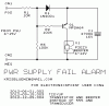
Ok so a couple months back I had a question about a circuit I couldn't get to work that was supposed to alert the user when the circuit it was attached to lost power. We couldn't figure it out but KrisBlue, a user on here was kind enough to draw up a different circuit for me to use.

It works great, and he kindly explained how it worked, but after revisiting said circuit, I got curious and starting removing certain components to see if it would still function. It does, and now I'm terribly confused as to why and was wondering if someone could it explain its operation to me.

Here it is.
 

Attachments

  • Kong1.jpg
    Kong1.jpg
    22 KB · Views: 152

kong

Sep 26, 2010
122
Joined
Sep 26, 2010
Messages
122
By now I have removed every component but the protective 10 ohm resistor, the 1n4001 diode, the 555, and the storage capacitor. Power is applied to host circuit, power is removed, and the output on the 555 goes high as the capacitor discharges into the 555--being blocked from going back to host circuit by the 1n4001.

I'm guessing there must be internal connections within the 555 that are allowing the output to go high, but I can't imagine why. I have the inputs all the inputs, beside the control, connected to either VCC or GND. I'm truly stumped.
 

KrisBlueNZ

Sadly passed away in 2015
Nov 28, 2011
8,393
Joined
Nov 28, 2011
Messages
8,393
Hi kong :)

So, you got curious and decided to start removing components to see whether it would still work. Well, I'm glad you're not my doctor!

You removed D2, R2 and C2, and it still beeps when the power fails?

I guess your piezo device must include an oscillator. You just need to apply DC to it and it beeps. I had assumed it needed to be driven with an AC signal; that's why the 555 is configured as an oscillator with R2 and C2.

As for why it works without D2, I don't know. If you post your current circuit, I could try to analyse the 555's internal circuitry to see how it might have that behaviour, but I don't see the point.

Since your piezo seems to be a DC-driven device, it would be possible to replace the 555 with a circuit containing one or two transistors, if that's what you want.
 

kong

Sep 26, 2010
122
Joined
Sep 26, 2010
Messages
122
Haha! Yeah that's probably a field I'll stay away from. :) I removed D2 but then found it behaving erratically when I removed power, so I ended up leaving D2 in (attached to pin 6 only, pin 2 is taken high)

I ended up replacing the piezo with a light, just to confirm an output without the need for oscillation circuitry.

I have a diagram, albeit horrible, but I can post something better later.

The circuit in the diagram actually works, believe it or not, and I have no idea why. I know that when I just attach a charged capacitor to the power supply pins of the 555, pin 3 goes high until the capacitor loses its charge. Must be something to do with the internal circuitry.
 

Attachments

  • diagram kong circuit.jpg
    diagram kong circuit.jpg
    25.4 KB · Views: 120

kong

Sep 26, 2010
122
Joined
Sep 26, 2010
Messages
122
Actually, the circuit works better the way you designed it. I think I'll stick with that. haha
 

kong

Sep 26, 2010
122
Joined
Sep 26, 2010
Messages
122
out of curiosity, though, how would one replace this circuit with one designed around transistors? I'm relatively new to electronics and this stuff fascinates me, so if you have time feel free to throw one up and I'll gladly look it over and ask more questions.

:)
 

KrisBlueNZ

Sadly passed away in 2015
Nov 28, 2011
8,393
Joined
Nov 28, 2011
Messages
8,393
Hmm, that's an interesting diagram. Once again, I'm glad you're not my doctor!

Yes, the 555 will work with that circuit, or without D2 if you tie pin 2 to pin 6. In that setup, it operates as a Schmitt trigger (Wikipedia it) with its trigger voltages (on pin 2/6) at 2/3 and 1/3 of its power supply voltage (which comes from the storage capacitor). When the actual power supply voltage drops below 1/3 of that voltage, the 555's output (pin 3) will go high, and it won't go low again until when (or if) the voltage on those pins rises above 2/3 of the 555's supply voltage, which won't happen while the power supply has failed.

Here's a circuit that will do the same thing using a transistor.

attachment.php


This circuit uses a PNP Darlington transistor. A PNP transistor is turned ON by a negative voltage on the base, measured relative to ("with respect to") the emitter voltage. The emitter voltage is held up by the storage capacitor. When the power supply fails, the input voltage drops towards zero (R3 helps this). Current through R2 pulls Q1's base voltage downwards, forward-biasing Q1's base-emitter junction and causing Q1 to conduct current from its emitter to its collector, which makes the beeper sound.

Q1 is a Darlington transistor (Wikipedia it too) which only needs a very low base current to turn ON. Unfortunately its collector-emitter voltage is higher than a normal transistor, so the beeper will not receive the full voltage of C1 across it.

Sorry if this is a bit incoherent. It's been a hard and hot Christmas day.
 

Attachments

  • KONG.004.GIF
    KONG.004.GIF
    3.7 KB · Views: 175

kong

Sep 26, 2010
122
Joined
Sep 26, 2010
Messages
122
No it's not incoherent at all! I always enjoy your thorough and polite responses. Thank you so much for explaining your circuits and taking the time to answer my questions.

I now fully understand the operation of the 555 circuit and am eager to test it without D2.

I will also build this transistor one.

I admire your ingenuity.

Have a wonderful holiday and a happy new year!
 
Top