Maker Pro
Maker Pro

Power supply failure alarm

KrisBlueNZ

Sadly passed away in 2015
Nov 28, 2011
8,393
Joined
Nov 28, 2011
Messages
8,393
Yes, your diode is shorted out. You need to move that stuff somewhere else.
 

kong

Sep 26, 2010
122
Joined
Sep 26, 2010
Messages
122
I put a 4.7 ohm resistor in series with the diode. Still nothing.

I don't know, I'm thinking of giving up on this little project. haha.
One last thing....does this circuit look correct to you? (bottom of page schematic) http://cr4.globalspec.com/thread/16962[/URL]
 

KrisBlueNZ

Sadly passed away in 2015
Nov 28, 2011
8,393
Joined
Nov 28, 2011
Messages
8,393
Your diode is shorted out because the power bus connects all the way along from the left edge to the right edge. You need to move the diode somewhere else, you can't put it on the horizontal power bus bars.
 

KrisBlueNZ

Sadly passed away in 2015
Nov 28, 2011
8,393
Joined
Nov 28, 2011
Messages
8,393
I mean you can't put both ends of it on the same horizontal bus bar, because that shorts it out. You need to move the right hand end onto one of the normal vertical sections of the breadboard.
 

kong

Sep 26, 2010
122
Joined
Sep 26, 2010
Messages
122
Good catch! see that's the kind of **** I mess up on, but unfortunately it still won't stop fading out. fuuuuuu
 

KrisBlueNZ

Sadly passed away in 2015
Nov 28, 2011
8,393
Joined
Nov 28, 2011
Messages
8,393
Since you've told me you're using a 555 to drive the piezo, I've got an easier way to handle this. I'll upload a schematic soon.
 

KrisBlueNZ

Sadly passed away in 2015
Nov 28, 2011
8,393
Joined
Nov 28, 2011
Messages
8,393
Power supply failure alarm with oscillator

This circuit combines the 555 oscillator with the power failure detection.
While power is present, C1 is kept charged via D1 and R1, and voltage through D2 prevents the 555 from oscillating.
When power fails, there is no longer any voltage on D2 so the oscillator starts running, and continues until C1 has discharged below the oscillator's minimum operating voltage.
The 555 oscillator circuit is probably slightly different from the one you're currently using. I use this circuit because it has one less resistor than the standard circuit. R2 in my circuit is equivalent to the resistor between pins 7 and 6 in the standard circuit. I've suggested 10K for this resistor but you can change it to match the value you were using. The resistor between pin 7 and VCC in the standard circuit isn't needed. The oscillator capacitor (C2) will be the same as you were using before.
If you don't have a 1N914 or 1N4148 for D2, you can use a 1N4001 the same as D1.
See I've specifically included a 10 ohm resistor in series with D1. It is a good idea.
Good luck!
 

Attachments

  • Kong.gif
    Kong.gif
    3.9 KB · Views: 128

kong

Sep 26, 2010
122
Joined
Sep 26, 2010
Messages
122
That looks great, thank you so much. I'm going to look forward to breadboarding that tomorrow as I'm wiped tonight, but I'll give it a go and report back.

Do you think a 4.7 ohm resistor will be ok for the diode protection or does it need to be 10 ohms? It's just I don't think I have any 10s on hand but I can pick some up if I need to
 

KrisBlueNZ

Sadly passed away in 2015
Nov 28, 2011
8,393
Joined
Nov 28, 2011
Messages
8,393
Oops I uploaded too soon. That's not the best way to arrange the circuit. The 555 could be damaged on power-up. Here's a better arrangement. All the comments from the previous post still apply.
 

Attachments

  • Kong.gif
    Kong.gif
    3.9 KB · Views: 120

KrisBlueNZ

Sadly passed away in 2015
Nov 28, 2011
8,393
Joined
Nov 28, 2011
Messages
8,393
You can use two 4.7 ohm resistors in series.
 

kong

Sep 26, 2010
122
Joined
Sep 26, 2010
Messages
122
Hmm....
still doesn't want to work.

Here is a photo of my breadboard set up...I moved the resistor and diode so that they don't short out on power up, that resistor is an 8.2 ohm

Everything else looks OK to me but maybe you will catch something I missed
 

Attachments

  • circ 2.jpg
    circ 2.jpg
    123.7 KB · Views: 104

KrisBlueNZ

Sadly passed away in 2015
Nov 28, 2011
8,393
Joined
Nov 28, 2011
Messages
8,393
You've made the same mistake as before - you're trying to use the red power bus for two separate signals, but you can't, because the connection runs all the way from the left end to the right end.
You need to move the three right-most connections off the red power bus and put them on a separate vertical strip on the breadboard. The three wires are the anode of the 1N4001, the anode of the 1N914, and the 8.2 ohm resistor.
 

kong

Sep 26, 2010
122
Joined
Sep 26, 2010
Messages
122
Like this? The white wire leading out goes to V+

I tried this and the piezo gave me a very little 'pop' like sound when I disconnect power!--so we're getting there.

But nothing that would alert anyone, much too short and quiet.
 

Attachments

  • once last.jpg
    once last.jpg
    103.4 KB · Views: 92

kong

Sep 26, 2010
122
Joined
Sep 26, 2010
Messages
122
Nevermind, tried a different piezo, and it lets out a fading wail as the power is disconnected and when the power is connected it's quiet! THANK YOU SO MUCH. IT WORKS. haha You've been so much help!
 

kong

Sep 26, 2010
122
Joined
Sep 26, 2010
Messages
122
So the circuit is working great, thanks again.

I'm just curious exactly how it works....how does a voltage through D2 keep the 555 from osc?

And how come when that voltage disappears the osc starts? Does it have something to do with the 0.7 voltage drop across the diode? Just curious.
 

KrisBlueNZ

Sadly passed away in 2015
Nov 28, 2011
8,393
Joined
Nov 28, 2011
Messages
8,393
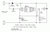
The 555's oscillation is controlled by the capacitor from pins 2 and 6 to ground, and the resistor that comes from pin 3. When it is oscillating, the voltage on pins 2 and 6 swings between two voltage thresholds, that are set at 2/3 and 1/3 of the supply voltage by an internal voltage divider inside the 555. Pin 3 is high (roughly +V) and the capacitor charges up to the 2/3 threshold. When pins 2 and 6 reach the 2/3 threshold, the 555 flips its output low, and the capacitor discharges to the 1/3 threshold, when the 555 flips its output high, and the cycle repeats. The time taken for the capacitor to charge and discharge creates the frequency that you hear in the piezo.
When voltage is present at the circuit input, the small diode holds pins 2 and 6 close to the supply rail, and even though the 555 drives its output low and tries to pull pins 2 and 6 towards ground with the resistor, it can't, and so it can't oscillate.
When the input voltage disappears, pins 2 and 6 are free to be pulled upwards and downwards by the resistor, and the circuit oscillates.
 

kong

Sep 26, 2010
122
Joined
Sep 26, 2010
Messages
122
Interesting. But why is a diode needed to do this? Couldn't you just connect pins 2 and 6 straight to the supply, bypassing it? Or is this a stupid question? haha
 

KrisBlueNZ

Sadly passed away in 2015
Nov 28, 2011
8,393
Joined
Nov 28, 2011
Messages
8,393
The diode is needed because the circuit's input voltage goes to zero when the power supply fails; if this was connected directly to pins 2 and 6 of the 555, the 555 wouldn't be able to oscillate because pins 2 and 6 would be being held at ground potential. The diode allows the incoming voltage to hold pins 2 and 6 and prevent oscillation when the voltage is present, and when the voltage disappears, the diode stops conducting and pins 2 and 6 are free to do their thing.
 
Top