Hello there!
This is my first post, so please be kind if I do something wrong here
I have a regulated circuit for a thermoelectric cooler (112.7 W, Impedance: 4.7 Ohms, max. Current 6 A, V max 29.8 V, max Temp change 74 °C). I know that this worked but it is somehow broken. So i need to build it anew but first i really want to understand how it works.
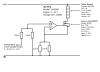
I have a controller that measures the temperature via a PT100 (the controller is connected to the "-" of the power supply unit and to the Op-Amp at "Stetigausgang") and a power supply unit with 30 V and 3 A max output current. The Op-Amp is powered by this supply. I want the thermoelectric cooler to be at 18 °C but that didn't work anymore. I got the circuit diagram by measuring shorts and resistors with a multimeter so i can't guarantee if this is correct, therefore I need to know if this works in principle and thus repairing it by just building it anew according to the diagram in the attachment.
This is how i understand it:
The controller puts a voltage on the connector "Stetigausgang" (sorry for the german...) if the temperature is too low. Then there's a difference in potential at the Op-Amp which amplifies this difference so that the gate-source voltage goes above the threshold voltage and thus letting the current (but how big is it and does that even matter if it is regulated?) flow from +30 V through two resistors and the thermoelectric cooler which then cools a bit down. The two resistors down below the inverting input produce a voltage from the current and the difference at the inputs of the op-amp becomes zero so it stops the current through the MOSFET. Then everything begins from the start according to the measurement of the controller and its output.
I assume the controller is doing its job properly so i don't wanna go into detail to this thing.
My questions are finally:
-How do i get these values for the resistors?
-Why are their values as they are?
-How important are the value of these resistors?
-Why do i even need this amplifying circuitry?
-Can i use this MOSFET instead: https://people.ece.cornell.edu/land...s/s2012/tcj26_ecs227/tcj26_ecs227/F12N10L.pdf
or this one: http://www.irf.com/product-info/datasheets/data/irli530n.pdf ??
And before you ask: yes the MOSFET is on a gigantic passive cooling element
Please clear things up for me and I hope I answered possible upcoming questions in advance. And thank you so much for your help!
Greetings!
This is my first post, so please be kind if I do something wrong here
I have a regulated circuit for a thermoelectric cooler (112.7 W, Impedance: 4.7 Ohms, max. Current 6 A, V max 29.8 V, max Temp change 74 °C). I know that this worked but it is somehow broken. So i need to build it anew but first i really want to understand how it works.
I have a controller that measures the temperature via a PT100 (the controller is connected to the "-" of the power supply unit and to the Op-Amp at "Stetigausgang") and a power supply unit with 30 V and 3 A max output current. The Op-Amp is powered by this supply. I want the thermoelectric cooler to be at 18 °C but that didn't work anymore. I got the circuit diagram by measuring shorts and resistors with a multimeter so i can't guarantee if this is correct, therefore I need to know if this works in principle and thus repairing it by just building it anew according to the diagram in the attachment.
This is how i understand it:
The controller puts a voltage on the connector "Stetigausgang" (sorry for the german...) if the temperature is too low. Then there's a difference in potential at the Op-Amp which amplifies this difference so that the gate-source voltage goes above the threshold voltage and thus letting the current (but how big is it and does that even matter if it is regulated?) flow from +30 V through two resistors and the thermoelectric cooler which then cools a bit down. The two resistors down below the inverting input produce a voltage from the current and the difference at the inputs of the op-amp becomes zero so it stops the current through the MOSFET. Then everything begins from the start according to the measurement of the controller and its output.
I assume the controller is doing its job properly so i don't wanna go into detail to this thing.
My questions are finally:
-How do i get these values for the resistors?
-Why are their values as they are?
-How important are the value of these resistors?
-Why do i even need this amplifying circuitry?
-Can i use this MOSFET instead: https://people.ece.cornell.edu/land...s/s2012/tcj26_ecs227/tcj26_ecs227/F12N10L.pdf
or this one: http://www.irf.com/product-info/datasheets/data/irli530n.pdf ??
And before you ask: yes the MOSFET is on a gigantic passive cooling element
Please clear things up for me and I hope I answered possible upcoming questions in advance. And thank you so much for your help!
Greetings!