Maker Pro
Maker Pro

Oscilloscope measurement problem

BlackMelon

Aug 7, 2012
188
Joined
Aug 7, 2012
Messages
188
Hi there,

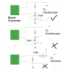
I've made a DC to DC step up (Boost) converter and I want to know its response to obtain its transfer function. The input is percentage of duty cycle (which I set it to be 60%) and the output is the output voltage. My voltage source is 12V dc battery and my load is 9.72Kohm resistor.

After I've connected my oscilloscope's probe and ground to the load, the output voltage didn't boost up. It stayed at 12V. I've changed a measurement tool to be a digital multimeter, everything worked correctly (but I couldn't obtain the graph response which such a tool).

Could you tell me why it happens this way?

PS: My oscilloscope has 10Mohms input resistance at 10X attenuation.

Thanks
BlackMelon
 
Last edited:

(*steve*)

¡sǝpodᴉʇuɐ ǝɥʇ ɹɐǝɥd
Moderator
Jan 21, 2010
25,510
Joined
Jan 21, 2010
Messages
25,510
Have you done some basic tests, like measuring the input and output voltage and the input current (all while the load is attached)?

I'm not sure I understand what "The input is percentage of duty cycle (which I set it to be 60%)" means. Perhaps you can also attach a copy of the circuit diagram?
 

(*steve*)

¡sǝpodᴉʇuɐ ǝɥʇ ɹɐǝɥd
Moderator
Jan 21, 2010
25,510
Joined
Jan 21, 2010
Messages
25,510
Oh, and have you by chance left the scope's input switched to AC coupled?
 

BlackMelon

Aug 7, 2012
188
Joined
Aug 7, 2012
Messages
188
Now I'll make the sentence "The input is percentage of duty cycle (which I set it to be 60%)" clear.

The voltage source is a DC 12V battery. I want to know that if I apply a square wave having a certain percentage of duty cycle to turn on a power MOSFET, how high the output voltage will be. In this case, I write a program to the Atmega8 to turn on the MOSFET with 60% square wave. If you look at the circuit I provided (file Schema3), the power MOSFET will be Q5.

The file schema 1 is an overview of the circuit.
Schema 2 shows how 5V power and clock are provided to Atmega8.
Schema 3 shows main components of a boost converter. 12V battery is applied to Vcc point (and Vcc of 7805 also). TC4421s are power MOSFET driver driving Q5 to boost output voltage up. Q6 and 500 ohm resistor are added to the circuit in the case that I've boosted the output voltage up very high before and want to reduce output voltage down to some level above 12V (Without Q6 and 500ohm, It can do the job but depends on RC time constant of the output resistance and the output capacitance which might be slow).
 

Attachments

  • 7segment.PNG
    7segment.PNG
    5.4 KB · Views: 89
  • Schema1.PNG
    Schema1.PNG
    16.2 KB · Views: 94
  • Schema2.PNG
    Schema2.PNG
    19.5 KB · Views: 119
  • Schema3.PNG
    Schema3.PNG
    18.3 KB · Views: 92

(*steve*)

¡sǝpodᴉʇuɐ ǝɥʇ ɹɐǝɥd
Moderator
Jan 21, 2010
25,510
Joined
Jan 21, 2010
Messages
25,510
It seems you're trying to use a simple boost topology. That's good. I like simple :)

There are a couple of issues:

  1. The voltage you get will not necessarily be determined by the duty cycle, it will be determined by a combination of a large number of factors
  2. The frequency as well as the duty cycle are important. If the frequency is too low (essentially if the ON time is too long) the inductor will saturate.
  3. In Schema3, Q5 is shown as a P channel device. There are two implications of this. First that a negative voltage wrt the source is required to turn it on, and secondly that the way you have shown it, the body diode will always be conducting.
Have you measured the current draw of this circuit? If your circuit is implemented as per your schematic, the current may be very large, or possibly the current will be very low due to the inductor having fused.

It is appropriate to use N Channel mosfets for Q5 and Q6,
 

BlackMelon

Aug 7, 2012
188
Joined
Aug 7, 2012
Messages
188
I'm sorry Q5 and Q6 are actually an N-ch MOSFETs lol. I've not measured current yet and I'll do it right away! (Cuz I didn't doubt at first that the 1Mohm input resistance of an oscilloscope could be a culprit drawing much current.)
 

BlackMelon

Aug 7, 2012
188
Joined
Aug 7, 2012
Messages
188
Steve, I've done measuring current and found very funny funny things. In the picture, in the first set up, The load (10Kohms resistor) drawn 7mA current and the converter boosted output voltage up to 70V correctly.
However, the second setup current is as shown. The converter can't boost voltage up, so the output voltage is equal to that of voltage source. No square wave turning the MOSFET Q5 and Q6 on. Q5 and Q6 drain voltages are on 12V (no switching occured) but Q5 heated itself up for unknown reason. The last set up also faced the same problem. I also have the same problem if I use an oscilloscope to measure output voltage directly without using an ammeter

PS:I'm curious that the problem might be from an alligator clip of oscilloscope probe. Every time I touch it, it shocks me. It might be sth. like voltage difference between the clip and the floor of my room. Can it bring charges or sth. weird from the floor up?
 

Attachments

  • Boost_Capture.PNG
    Boost_Capture.PNG
    13 KB · Views: 82

(*steve*)

¡sǝpodᴉʇuɐ ǝɥʇ ɹɐǝɥd
Moderator
Jan 21, 2010
25,510
Joined
Jan 21, 2010
Messages
25,510
Is it possible that your oscilloscope has a switchable 50 ohm impedance?

Use your multimeter to measure the resistance across the oscilloscope probe.

There is also a possibility that your power supply ground and your oscilloscope ground are connected in such a way that you're shorting the output.

Check to see if there is any continuity between either power supply connection and the oscilloscope ground lead.
 
Top