Maker Pro
Maker Pro

oscillator doesn't oscillator as I expect

duke37

Jan 9, 2011
5,364
Joined
Jan 9, 2011
Messages
5,364
Things are complicated, there is capacitance between turns so this will alter the distribution of current in the inductance. Also the effect of the capacitance will vary with frequency.

I measure the inductance with an inductance meter and also measure the self resonant frequency with a grid dip oscillator, then calculate what capacitance an ideal inductance would need to have in parallel to get the same effect. This is only an approximation.

An interesting exercise is to design an anode choke for a high power radio transmitter running at various frequencies.Sections of the choke can resonate and much smoke can be produced. Recommended designs are complicated with the inductance split into sections so that there are no resonances on required frequencies.
 

long

Mar 31, 2014
19
Joined
Mar 31, 2014
Messages
19
Hi, duke37:

thank you a lot for pointing this out.

This is very interesting, if an inductor will behave like a capacitor when frequency goes beyond self-resonance point, that means it will no longer be "blocking" high frequency, which is quite some contrary to what people usually takes inductor as. This is definitely good to know!

Just curious, how much capacitance you see when the inductor gets into self-resonant state? how many pf/uH? or nf/uH?

Things are complicated, there is capacitance between turns so this will alter the distribution of current in the inductance. Also the effect of the capacitance will vary with frequency.

I measure the inductance with an inductance meter and also measure the self resonant frequency with a grid dip oscillator, then calculate what capacitance an ideal inductance would need to have in parallel to get the same effect. This is only an approximation.

An interesting exercise is to design an anode choke for a high power radio transmitter running at various frequencies.Sections of the choke can resonate and much smoke can be produced. Recommended designs are complicated with the inductance split into sections so that there are no resonances on required frequencies.
 
Last edited:

long

Mar 31, 2014
19
Joined
Mar 31, 2014
Messages
19
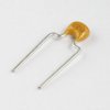
I find a picture of the cap from internet, same as what I used.

Glad you are making progress. An inductor will change it inductance as the current distribution changes due to skin effect. But at those frequencies and the small diameter wire you are using I doubt it will change much. It's more likely to be the capacitor. What type of capacitor are you using.
Adam
 

Attachments

  • capacitor-22pf-300.JPG
    capacitor-22pf-300.JPG
    4.6 KB · Views: 172

Arouse1973

Adam
Dec 18, 2013
5,178
Joined
Dec 18, 2013
Messages
5,178
Things are complicated, there is capacitance between turns so this will alter the distribution of current in the inductance. Also the effect of the capacitance will vary with frequency.

I measure the inductance with an inductance meter and also measure the self resonant frequency with a grid dip oscillator, then calculate what capacitance an ideal inductance would need to have in parallel to get the same effect. This is only an approximation.

An interesting exercise is to design an anode choke for a high power radio transmitter running at various frequencies.Sections of the choke can resonate and much smoke can be produced. Recommended designs are complicated with the inductance split into sections so that there are no resonances on required frequencies.

High Duke
Oh I thought the capacitance of a coil was effectively across the coil, which is why the coil self oscillates. I thought only when skin effect started to play a part did the magnetic flux distribution in the coil rise to the surface due to eddy currents.

Which is why the amount current in a coil doesn't effect the inductance because inductance is the ratio of current and magnetic flux. So when you increase the current the flux goes up but they still maintain the same approximate ratio.

But the total impedance will go down with a parallel capacitance as frequency goes up which is what can fool the inductance meter into thinking it is a smaller inductor than it is if the equipment was using too higher frequency.

I didn't know the capacitance actually changed the inductance of the coil.

Thanks
Adam
 

duke37

Jan 9, 2011
5,364
Joined
Jan 9, 2011
Messages
5,364
I do not think that the frequency affects the inductance greatly but it will affect the effective reactance.
Short verticle aerials often have an inductance at the bottom to bring it to resonance. It is recommended that the coill is made with spaced turns to reduce the interwire capacitance and increase the Q.

Above the resonance frequency the capacitive reactance overcomes the inductive reactance. The effects will depend on the coil construction.
At audio frequencies capacitance may not be a problem but high quality valve audio amplifiers have transformers with segmented interleaved windings to maintain response at high audio frequencies.

At VHF coils and capacitor are often replaced with tuned lines where the capacitance and inductance are distributed along the line.

An analogy occurs with capacitors which have an inductance in series, so to bypass a power line, you might use a 1000µf capacitor, a !00nF capacitor and a 100pF capacitor with very short leads to be effective at a wide range of frequencies.

A theoretical diagram can differ considerably from actuality.
 

long

Mar 31, 2014
19
Joined
Mar 31, 2014
Messages
19
So go back to tank circuit, there are two lines of seemingly conflicting things which confuse me:

1. the inductor has self capacitance, this self capacitance is parallel to the C of the tank circuit, so we will see the resonance frequency lower because the overall capacitance(self capacitance of inductor + C of tank) is higher. In this case, self-capacitance is more like in parallel with the inductor.

2. the self capacitance will reduce the effective inductance of the inductor, this will make the resonance freq of the tank to be higher because L is smaller. In this case, the self capacitance is more like in series with the inductor, other than in parallel.

Which one is right? or both wrong? I am afraid that I should take the second view.

I do not think that the frequency affects the inductance greatly but it will affect the effective reactance.
Short verticle aerials often have an inductance at the bottom to bring it to resonance. It is recommended that the coill is made with spaced turns to reduce the interwire capacitance and increase the Q.

Above the resonance frequency the capacitive reactance overcomes the inductive reactance. The effects will depend on the coil construction.
At audio frequencies capacitance may not be a problem but high quality valve audio amplifiers have transformers with segmented interleaved windings to maintain response at high audio frequencies.

At VHF coils and capacitor are often replaced with tuned lines where the capacitance and inductance are distributed along the line.

An analogy occurs with capacitors which have an inductance in series, so to bypass a power line, you might use a 1000µf capacitor, a !00nF capacitor and a 100pF capacitor with very short leads to be effective at a wide range of frequencies.

A theoretical diagram can differ considerably from actuality.
 
Last edited:

Arouse1973

Adam
Dec 18, 2013
5,178
Joined
Dec 18, 2013
Messages
5,178
I think the self capacitance of your small coil and the frequency of your circuit it is not going to effect the resonant frequency much. The apparent inductance Duke was on about I think is what the test equipment would show because of the effect of the capacitance and Z of the whole circuit. If the tester is outputting too higher frequency then it could be fooled into giving a lower reading. In my view and I think Duke mentioned above the capacitance does not change the actual inductance just a measuring device might think it's lower.
Thanks Adam
 

long

Mar 31, 2014
19
Joined
Mar 31, 2014
Messages
19
I am not very sure if the existence of "test equipment" will change the nature of this problem.

Let us do a mental exercise:

Assume I have a tank circuit, with L and C. The theoretical resonance freq is f_r = 1/2*pi*sqrt(L*C).

And assume f_r is a large number that the inductor L will have some observable self-capacitance C_l at f_r which can be roughly figured out by previous post by Duke37.

So in this mental exercise, I don't expect the tank will really resonate at freq f_r. So my question is: if the tank's actual resonate at f_R, will f_R > f_r or f_R < f_r?
 

duke37

Jan 9, 2011
5,364
Joined
Jan 9, 2011
Messages
5,364
The reality is that it is not a LC circuit but that there are multiple circuits with coupling inductance and capacitance between every turn.
If you measure the inductance at low frequencies, the capacitance effects will be negligible. If you measure at high frequencies, the capacitances may prodominate.

The capacitance effect will depend on the coil construction. It may be a simple solenoid or a solenoid with spaced turns it may be separated into mini banks which are wave wound.

A magnetic core will allow fewer turns and lower wire resistance and interturn capacitance. It is all rather complicated and there are many optimum solutions.
 

long

Mar 31, 2014
19
Joined
Mar 31, 2014
Messages
19
Thank you for clarifying. Now I get it :p

The reality is that it is not a LC circuit but that there are multiple circuits with coupling inductance and capacitance between every turn.
If you measure the inductance at low frequencies, the capacitance effects will be negligible. If you measure at high frequencies, the capacitances may prodominate.

The capacitance effect will depend on the coil construction. It may be a simple solenoid or a solenoid with spaced turns it may be separated into mini banks which are wave wound.

A magnetic core will allow fewer turns and lower wire resistance and interturn capacitance. It is all rather complicated and there are many optimum solutions.
 
Top