Maker Pro
Maker Pro

Old RCA CRT Console TV Repair

zander21510

Aug 21, 2013
4
Joined
Aug 21, 2013
Messages
4
Hello, I'm currently trying to restore an old RCA console television to use with my retro game consoles. My uncle found it for me in excellent cosmetic condition, and was apparently used up until a few years ago, taken care of in an old woman's house till she passed away. Sticker on the back says manufactured in 1986, it's a RCA Colortrak 2000- very high end for the day.

So the problem it's having, from the research I've done, seems to be consistent with some bad capacitors. There are some lines on the top of the screen, and it will lose power randomly before coming back on. I would say it works fine 60% of the time, the other 40% the screen goes out for a few minutes, and comes back on intermittently.

I'm fairly comfortable with soldering & I want to try to replace the capacitors, problem is, there are SO MANY and I'm not sure where to start. From my research, I should be looking for bulged or leaking capacitors, but I haven't found any except for just one that seems like it's slightly bulged on the top.

The nice thing about this TV though, is it has a bunch of reference stickers on the inside of the cabinet, that look like diagrams. Over my head for sure, but hopefully someone can make something out of it?

I've attached pictures of the main board inside the cabinet, along with the reference stickers on the side, and circled the one capacitor that seems bulged. If someone could help me pick out a few capacitors to start with to replace, it would help me not pick ones that won't make a difference and reduce the possibility of me messing something up. Let me know if you need more/better pictures or want to see the other boards. Thanks!

Full Cabinet:
2017-01-29 10.40.18.jpg Diagrams
2017-01-29 10.39.02.jpg 2017-01-29 11.02.17.jpg 2017-01-29 10.39.17.jpg 2017-01-29 10.39.26.jpg
Right side of main board (has a smaller board stacked on top)
2017-01-29 11.03.12.jpg Closer look underneath right side of main board
2017-01-29 11.03.19.jpg Middle view of main board
2017-01-29 11.03.26.jpgLeft view of main board
2017-01-29 11.03.33.jpg
Circled capacitor is slightly bulged, view of left side of main board
2017-01-29 10.40.33.jpg
Circled capacitor is slightly bulged, top view of main board. 2017-01-29 11.03.41.jpg
 

Harald Kapp

Moderator
Moderator
Nov 17, 2011
13,749
Joined
Nov 17, 2011
Messages
13,749
I want to try to replace the capacitors, problem is, there are SO MANY and I'm not sure where to start.
It's typically the electrolytic capacitors that fail after a few years due to loss of electrolyte. That narrows down the number of caps you have to inspect and change. An electrolytic capacitor is the type you circled in one of your images and a bulge is a sure sign of loss of electrolyte due to outgassing. Identify these capacitors, specially in the power supply section and replace them. The important parameters are capacity and voltage. Match capacity exactly. For the voltage rating you can use ones with a higher rating, never with a lower rating. Note the polarity (usually indicated by a white bar with '-' signs in it on the side of the capacitor)a nd make sure the repalcements are soldered in the same orientation (there may even be marks on the PCB to help putting in the capacitors in the right orientation - if not make your own marks).
Note that modern electrolytic capacitors may be noticeably smaller at the same capacity/voltage rating as the older ones due to improved technology. This is no problem, only you may have to bend the pins a bit.

For your safety: Make sure all capacitors are fully discharged before working on them. Disconnect the TV from mains power and let it sit for some time (preferably over night) - some capacitors may store charge at high voltages for quite some time. The efffect can be at the least unpleasant if not worse.
 

shrtrnd

Jan 15, 2010
3,876
Joined
Jan 15, 2010
Messages
3,876
Harald Kapp pretty-much covered the first things to do.
My added input is to stay away from the red 'anode' cable that plugs in the back top of the picture tube itself and
runs down to the flyback transformer. The picture tube acts as it's own high voltage 'capacitor'. Even when the
TV is unplugged and turned-off, it stores a charge of several thousand volts, and you don't want to get hit by
that discharge voltage.
 

DR1

Apr 20, 2024
6
Joined
Apr 20, 2024
Messages
6
1713624446908.png
1713624549858.png
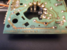
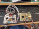
Hello,I need the RCA CRT Circuit board on the right! The model number is 1422078-6. RCA console TV!
 

73's de Edd

Aug 21, 2015
3,629
Joined
Aug 21, 2015
Messages
3,629
Sir DR1 . . . . .

Question ?

WHY for do you need that Ruh Cee Aeee PW5000 circuit board, since it is only having the RED-BLUE-GREEN kine drivers on it and a video choke and associated support discrete resistors and caps on it, with the only SNAFU, I see about the board, being on the right, with 3 pins of the kine socket that are spun around and misaligned . . . . nothing that a mechanica-electronica competent person couldn't easily correct.
Your new / er PW5000 on the left . . . . . even has a VIRGIN donor tube socket . . . fully housed , no less, that could be swapped out.

I strongly feel that there isn't a rats anal orifice chance in Hades, of you ever finding another of that right side board.

What makes you want to fault it ? . . . . . describe its affectation, when being installed in the TV..

1713665608438.png
BTW . . . . .that one TRW Cermet block power resistor dates the unit as being post 1985-6 vintage.


73's de Edd . . . . .
 

DR1

Apr 20, 2024
6
Joined
Apr 20, 2024
Messages
6
Sir DR1 . . . . .

Question ?

WHY for do you need that Ruh Cee Aeee PW5000 circuit board, since it is only having the RED-BLUE-GREEN kine drivers on it and a video choke and associated support discrete resistors and caps on it, with the only SNAFU, I see about the board, being on the right, with 3 pins of the kine socket that are spun around and misaligned . . . . nothing that a mechanica-electronica competent person couldn't easily correct.
Your new / er PW5000 on the left . . . . . even has a VIRGIN donor tube socket . . . fully housed , no less, that could be swapped out.

I strongly feel that there isn't a rats anal orifice chance in Hades, of you ever finding another of that right side board.

What makes you want to fault it ? . . . . . describe its affectation, when being installed in the TV..

View attachment 63404
BTW . . . . .that one TRW Cermet block power resistor dates the unit as being post 1985-6 vintage.


73's de Edd . . . . .
First off on the right,I am trying to see what you are talking about. Plus with the connector being,Looks like it burned off,especially with the burnt mark on the plastic shield that goes behind this board,I thought the board might be bad.You can see the white CRT connector is gone and only prongs left. Plus the board on the left has a different set up with some different components and how some are set up and wiring is different.
 

DR1

Apr 20, 2024
6
Joined
Apr 20, 2024
Messages
6
Sir DR1 . . . . .

Question ?

WHY for do you need that Ruh Cee Aeee PW5000 circuit board, since it is only having the RED-BLUE-GREEN kine drivers on it and a video choke and associated support discrete resistors and caps on it, with the only SNAFU, I see about the board, being on the right, with 3 pins of the kine socket that are spun around and misaligned . . . . nothing that a mechanica-electronica competent person couldn't easily correct.
Your new / er PW5000 on the left . . . . . even has a VIRGIN donor tube socket . . . fully housed , no less, that could be swapped out.

I strongly feel that there isn't a rats anal orifice chance in Hades, of you ever finding another of that right side board.

What makes you want to fault it ? . . . . . describe its affectation, when being installed in the TV..

View attachment 63404
BTW . . . . .that one TRW Cermet block power resistor dates the unit as being post 1985-6 vintage.


73's de Edd . . . . .
I did swap out the tube socket. Show screen grab of the snafu.
 

73's de Edd

Aug 21, 2015
3,629
Joined
Aug 21, 2015
Messages
3,629
Sir DR1 . . . . .

Firstly . . .
Plus with the connector being,Looks like it burned off,especially with the burnt mark on the plastic shield that goes behind this board,
Did not make any sense and register with me at all .
I don't have the benefit of viewing . . .the burnt mark on the plastic shield that goes behind this board, . . .to be able to a specific component against or near to that burnt mark.

Herewith . . . . . . .illustrations, marked up of "Show screen grab of the snafu."

PICKT - CHOOR CITY . . . . .


RCA-Kine-Driver-Board.png

Top pic is of your largest but it is out of focus and has poor depth of field. The top left inset clarifies a socket pins profile . . .with the two shown . . . a slot in a pin rides across a CRT pin as the socket is slipped onto the CRT neck and its surrounding pins ..
The silver lines radial orientations towards the RED center of the kine neck, depict each slotted connector pins alignment.
Examining the first two pins on the left, they seem in order, then the next one .?. . . . .where is it ? OR am I seeing it being GROSSLY misaligned, and turned 90 degrees off to the right !
The remaining pins are not usable in making a DEFINITIVE evaluation, so lets move on to your other smaller photo. But lets also catch the
BLUE rectangle which is referencing to a connection that has to protrude down into a plastic channel in the picture tube neck connections where there are two redundant pins for receiving ~7.5 Kv focus voltage. That connector is affixed to the two RED X markers.
Now you can look down to the lower left photo, which was snipped from the more technically sophisticated chassis of the earlier original poster. BUT, you both use the same picture tube.
That white connector plugs down into that mentioned CRT cavity and is mechanically clipped down at the RED X points.
There is an open air spark gap with its two rounded electrodes. The flagged 7.5K v focus wire goes down into the kine cavity and connects.
The open air spark gap has a ground wire going to it.
New CRT's have HIGH tendencies of snap-crackle-pop and BANGS ! for the first weeks of use, until its eventual "burn in".
That spark gap spacing and its flash over threshold protects any kine big bang, from feeding over to the focus circuitry and crunching the
" inaccessible, potted" rectifier diodes in the Integrated High Voltage Transformer.
A CONTINUANCE . . .
Now lets start pin connections on the second smaller picture.
GREEN star reference is to the stamped brass ring that encircles the outer periphery of the 7 pins on that socket. Kine flash overs can also relate to all of these pin connections, so the defined and established spacing of them to that brass ring also makes spark gaps for each of those pins.
Starting to the right from the GREEN star the closest pin, and the next two seem to orient their groove properly towards the RED circle center tube neck locus. The same seems true for the 4th one (RED circle) . . .BUT . . .is it pushed back ?
Now the fifth one ? . .? . . ? WOW ! is its slot aligned up on that cermet resistor (RED arrow path) ? . . . its off ~90 degrees to the right.
Next is the 6th pin which also s e e e e e ms to be correct.
Then there is the last and 7th pin . . .WHOOPS ! . . .look at its RED arrow path, off 90+ degrees.
AND it just seems that both pins 5 and 7 are now resting atop the BRASS grounding ring and shorting themselves out to ground ? right ?

OK now, . . . . . is I right . . . . . or is I wrong ? or am, I just . . . . . . . working from squirrelly reference photos ?

Thaaaaassssit . . . . .

73's de Edd . . . . .

Blonde Joke . . . . . .

Two bowling teams,
One Team is all Blondes and the other team is all Brunettes.
They charter a double-Decker bus for a weekend trip to Louisiana .
The Brunette team rode on the bottom of the bus, and the Blonde team rode
on the top level.
The Brunette team down below really whooped it up, having a great time,
when one of them realized she hadn't heard anything from the Blondes
upstairs. She decided to go up and investigate.

When the Brunette reached the top, she found all the Blondes in fear,
staring straight ahead at the road, clutching the seats in front of them with
white knuckles.

The brunette asked, 'What the heck's going on up here? We're having a
great time downstairs!'
One of the Blondes looked up at her, swallowed hard and whispered.

"YEAH, BUT YOU'VE GOT A DRIVER!"
 

DR1

Apr 20, 2024
6
Joined
Apr 20, 2024
Messages
6
Sir DR1 . . . . .

Firstly . . .
Plus with the connector being,Looks like it burned off,especially with the burnt mark on the plastic shield that goes behind this board,
Did not make any sense and register with me at all .
I don't have the benefit of viewing . . .the burnt mark on the plastic shield that goes behind this board, . . .to be able to a specific component against or near to that burnt mark.

Herewith . . . . . . .illustrations, marked up of "Show screen grab of the snafu."

PICKT - CHOOR CITY . . . . .


RCA-Kine-Driver-Board.png

Top pic is of your largest but it is out of focus and has poor depth of field. The top left inset clarifies a socket pins profile . . .with the two shown . . . a slot in a pin rides across a CRT pin as the socket is slipped onto the CRT neck and its surrounding pins ..
The silver lines radial orientations towards the RED center of the kine neck, depict each slotted connector pins alignment.
Examining the first two pins on the left, they seem in order, then the next one .?. . . . .where is it ? OR am I seeing it being GROSSLY misaligned, and turned 90 degrees off to the right !
The remaining pins are not usable in making a DEFINITIVE evaluation, so lets move on to your other smaller photo. But lets also catch the
BLUE rectangle which is referencing to a connection that has to protrude down into a plastic channel in the picture tube neck connections where there are two redundant pins for receiving ~7.5 Kv focus voltage. That connector is affixed to the two RED X markers.
Now you can look down to the lower left photo, which was snipped from the more technically sophisticated chassis of the earlier original poster. BUT, you both use the same picture tube.
That white connector plugs down into that mentioned CRT cavity and is mechanically clipped down at the RED X points.
There is an open air spark gap with its two rounded electrodes. The flagged 7.5K v focus wire goes down into the kine cavity and connects.
The open air spark gap has a ground wire going to it.
New CRT's have HIGH tendencies of snap-crackle-pop and BANGS ! for the first weeks of use, until its eventual "burn in".
That spark gap spacing and its flash over threshold protects any kine big bang, from feeding over to the focus circuitry and crunching the
" inaccessible, potted" rectifier diodes in the Integrated High Voltage Transformer.
A CONTINUANCE . . .
Now lets start pin connections on the second smaller picture.
GREEN star reference is to the stamped brass ring that encircles the outer periphery of the 7 pins on that socket. Kine flash overs can also relate to all of these pin connections, so the defined and established spacing of them to that brass ring also makes spark gaps for each of those pins.
Starting to the right from the GREEN star the closest pin, and the next two seem to orient their groove properly towards the RED circle center tube neck locus. The same seems true for the 4th one (RED circle) . . .BUT . . .is it pushed back ?
Now the fifth one ? . .? . . ? WOW ! is its slot aligned up on that cermet resistor (RED arrow path) ? . . . its off ~90 degrees to the right.
Next is the 6th pin which also s e e e e e ms to be correct.
Then there is the last and 7th pin . . .WHOOPS ! . . .look at its RED arrow path, off 90+ degrees.
AND it just seems that both pins 5 and 7 are now resting atop the BRASS grounding ring and shorting themselves out to ground ? right ?

OK now, . . . . . is I right . . . . . or is I wrong ? or am, I just . . . . . . . working from squirrelly reference photos ?

Thaaaaassssit . . . . .

73's de Edd . . . . .

Blonde Joke . . . . . .

Two bowling teams,
One Team is all Blondes and the other team is all Brunettes.
They charter a double-Decker bus for a weekend trip to Louisiana .
The Brunette team rode on the bottom of the bus, and the Blonde team rode
on the top level.
The Brunette team down below really whooped it up, having a great time,
when one of them realized she hadn't heard anything from the Blondes
upstairs. She decided to go up and investigate.

When the Brunette reached the top, she found all the Blondes in fear,
staring straight ahead at the road, clutching the seats in front of them with
white knuckles.

The brunette asked, 'What the heck's going on up here? We're having a
great time downstairs!'
One of the Blondes looked up at her, swallowed hard and whispered.

"YEAH, BUT YOU'VE GOT A DRIVER!"
1713797378856.png
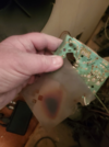
Here is what I am talking about,burnt mark. The shield that goes behind CRT board. Thank You for your response!
 

73's de Edd

Aug 21, 2015
3,629
Joined
Aug 21, 2015
Messages
3,629
Sir DR1 . . . . .

Initially, swing that plastic shield rotary positioning back around to where it was, and it will then align up with the kine's socket end.
My HIGHLY educated estimation . . . . . is that is merely being the result of heating of that area, over potential decades of run time.
With that SPECIFIC family of plastic sheet being used, just responding in that way, when exposed to that level of heat and cumulative time of use..
Prior years had the use of a like, thin fiberboard cover that had bends / folds on ends fashioned into tabs to slip into slots on the pcb.
HEAT exposure to that cover type had it bone dry, so that the tabs would break off if even touched.
An intermediate fix was the use of this clip ***** to affix the fiberboard, but the fiberboard still would tear off
*****
1713807167008.pngcanoe clip
Thus the final resorting to of ties to re affix the detached sheet to the pcb, such as yours is now . . . . . and is using bead ties.

ASIDE . . . .
Using your last forthcoming fotie-graff . . . concentrate on the first bend of your index finger and the pcb area near and around and you see darker contaminants deposited or electrostatically precipitated there.
Move up to the RED high voltage wire going to the ultor cap at center point of the picture tube. Stop just short of that cap and get some white toilet paper squares to further down fold into a smaller pad and also get some rubbing alcohol to dampen the pad. Grip the wire inside that wetted tab and move to cleanse about 3 inches of that red wire exterior.
That . . .my friend . . . . is the degree of environmental air contamination that unit has been subjected to in its running lifetime . . . .being electrostatically precipitated on that wire.


Thaaaasssssit . . .

73's de Edd . . . . . .
 
Last edited:
  • Like
Reactions: DR1

DR1

Apr 20, 2024
6
Joined
Apr 20, 2024
Messages
6
Initially, swing that plastic shield rotary positioning back around to where it was, and it will align up with the kine's socket end.
My HIGHLY educated estimation . . . . . is that is merely being the result of heating of that area, over potential decades of run time.
That SPECIFIC family of plastic sheet used, just responds that way to exposed level of heat and cumulative time of use..
Prior years had the use of a like, thin fiberboard cover that had bends / folds on ends fashioned into tabs to slip into slots on the pcb.
HEAT exposure to that cover type had it bone dry, so that the tabs would break off if touched.
Thus the resorting to of ties to re affix the detached sheet to the pcb, such as yours now . . . . .is using bead ties.
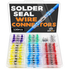
I just fastened the shield back on with the cable ties,this morning. I bought those solderless connectors to wire that board back into the TV. https://www.amazon.com/dp/B0CD4CRHD8?psc=1&ref=ppx_yo2ov_dt_b_product_details 1713806866400.png
 

73's de Edd

Aug 21, 2015
3,629
Joined
Aug 21, 2015
Messages
3,629
I was initially thinking . . . .Why would he / anyone do a STOOOOOPID thing like that ? . . . . . .live and learn and SAVE ? X $15.00 X ? amount of dollars !
A la . . . . .

1713810064567.png
 
Last edited:
Top