-
Categories
-
Platforms
-
Content
So I assume it was dry joints somewhere in the module...??
I've always herd it referred to as a "cold joint".Since I am so new at this I have no idea, other than they appeared to be intact/no splits, etc to my naked eye. You guys would know more. I guess they call it dry joints. Learned something.
It is usually better to *first* ask (or search for as I did to find the link below) automotive circuit questions in a forum for the respective model and generation of vehicle, where fellow owners have probably already encountered the fault once a vehicle gets older, and may have wiring diagrams to show you where to probe for loss of power (or a voltage drop across a now-resistive portion of the circuit), or if it is getting all the way to the motor and then either motor or mechanism jambed or gears stripped.
This type of headlight benefits greatly from lubrication to decrease strain, and power needed to actuate. I would do that first since it needs done anyway if you haven't already.
Here's a topic:
https://www.thirdgen.org/forums/tech-general-engine/216154-87-92-firebird-headlight.html
Thanks for this link! I found many useful answers for myself, since I bought a new car and I just can't figure it out (
With&Respect
Jossy
employee monitoring
They are all lead free for a long time now from what i see which is nice imo. I prefer to avoid lead when ever I can. I'm much to sloppy to have to worry about proper handling of it.except, I don't know, maybe vehicles are exempt from ROHS lead free mandates? I do know that I'm using leaded solder whenever I work on one, and wire management is important, can't have harnesses flopping around with every vehicle vibration.
People,
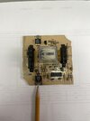
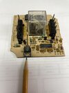
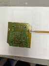
Have a 1987 Sunbird GT,with headlight "doors" that open and close via a module controller. A similar one is here, at about 6- 1/2 minutes into the video:
The video shows the solder joints for the pin connectors may be old/bad, and he resolders it. But mine has no visible cracks/bad spots. is there a way to troubleshoot the pins via an ohmmeter/other device?
I hate to indiscriminitely start heating up joints with no clear goal. never done this before.
Thanks, people.
I was afraid of that, as I am so bad at posting pictures- but I will ask help from my son, he is good at that. Could be a day or so, but meanwhile, the picture will not show much different than the youtube video, at the 8:15 mark. Only difference will be some brownish discoloration, as I mentioned. Does the video not come up? I actually did not try it, I assumed it would record for yous.Show a clear photo of your board problem
Great vid, took a while to reach the repair but the car is nice...! re-itterate. Regular cheap electrical solder, usually works fine, but things like motor relays usually require a stronger and higher silver content solder that requires a bit hotter than normal iron. This stuff was built by a robot that has a tip that was designed to flow the heavier solder without overheating the board or melting the bonding agent between the plating and the PCB. It takes a robot about .6 of a second to put this together, do you think you can move that fast? Then turn up the heat, get a good drop on your tip and apply to the connector, and not to the board. the solder will flow to the board when the solder there melts... just a pointer in the right direction>>>>> low heat to board>>>>high heat to connecting lug.
Was it a MT or an AT?I bought a '89 Sunbird GT for my wife's first car. She loved the turbo power and often said, '"Why is everybody so far behind?"
The headlight doors worked fine for the many years that we had the car.
Well, it does connect to the tab of the transistor which is usually the collector of the transistor, same as the centre pin of the 3 pins, (depending on type model etc) ..............BUT that track is not connected to anything else aside from the transistor tab.So, this connector is the ground lug, right?