roughshawd
- Jul 13, 2020
- 470
- Joined
- Jul 13, 2020
- Messages
- 470
I see a lot of yootoob videos where a guy wires up some pots and some resistors and diodes to some mosfets, and builds a voltage and amperage controller.
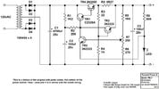
I am rebuilding a bench ps and was wondering if this would be a good circuit to put in for variable power and current?
I am rebuilding a bench ps and was wondering if this would be a good circuit to put in for variable power and current?