Oi!
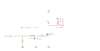
I am using an N-channel MOSFET (IRFZ24) to turn on a set of LEDs+other stuff (powered from 12V). Drain of the MOSFET is connected to the LEDs, source is grounded, and I use an Arduino’s digital pin to give either 5V or 0V to the Gate.
My question is about amps and burning. From their data sheets, Arduino can only handle 40mA through I/O pins. Now, while the MOSFET would draw practically nothing while in a static state, the dynamic state bothers me. Looking at page 2 of the MOSFET’s data sheet, the rise time is 58ns, and since I need to charge the gate by ~10-20nC, the current = dC/dt ~ 10/58 ~ 0.2A, higher than 40mA, hence I am killing the I/O pin.
Is my logic above correct? Am I gonna draw that much current? Would that fry my I/O pins? If no, why? If yes, what can I do to prevent that? Would throwing in a resistor to the Gate help (kinda like an RC circuit logic)? Am I being overly paranoid?
I’d really appreciate any advice and enlightenment") I am just a student seeking understanding; and I don’t want to burn **another** Arduino.
I am just a student seeking understanding; and I don’t want to burn **another** Arduino.
Cheers,
Savva
I am using an N-channel MOSFET (IRFZ24) to turn on a set of LEDs+other stuff (powered from 12V). Drain of the MOSFET is connected to the LEDs, source is grounded, and I use an Arduino’s digital pin to give either 5V or 0V to the Gate.
My question is about amps and burning. From their data sheets, Arduino can only handle 40mA through I/O pins. Now, while the MOSFET would draw practically nothing while in a static state, the dynamic state bothers me. Looking at page 2 of the MOSFET’s data sheet, the rise time is 58ns, and since I need to charge the gate by ~10-20nC, the current = dC/dt ~ 10/58 ~ 0.2A, higher than 40mA, hence I am killing the I/O pin.
Is my logic above correct? Am I gonna draw that much current? Would that fry my I/O pins? If no, why? If yes, what can I do to prevent that? Would throwing in a resistor to the Gate help (kinda like an RC circuit logic)? Am I being overly paranoid?
I’d really appreciate any advice and enlightenment
I am just a student seeking understanding; and I don’t want to burn **another** Arduino.Cheers,
Savva