Maker Pro
Maker Pro

Measuring the inductance of a wirewound resistor

(*steve*)

¡sǝpodᴉʇuɐ ǝɥʇ ɹɐǝɥd
Moderator
Jan 21, 2010
25,510
Joined
Jan 21, 2010
Messages
25,510
One of my projects is to make a passive load.

Sounds easy, right? And it is. Get some high power resistors (50W) attach them to a big heatsink, and Bob's your uncle.

My load will have 5% 0.01, 0.1, 1, 10, 100, 1k, and 10k at 50W (except for 1R and 100R which will be 200W).

And I thought -- I wonder about the inductance of these resistors.

I measure the 1R -- 0.6uH, 10R -- 3.5uH, 100R -- 404mH (what?!), 1k -- 29H (you're kidding, right?), and 10k -- over range.

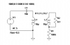
And so I think -- what is the reason for this. The answer is clearly that the meter is assuming the resistance is close to zero, and so the resistance is being included in the reactance, and so the inductance measures high.

That's my working theory. And it just so happens that the device reports the frequency, so maybe I can compute the real part of the reactance, subtract the resistance and work back to a better guess for the inductance.

What do you think the odds are?

And what is an alternative method of measuring the inductance that will not be sensitive to the resistance?
 

(*steve*)

¡sǝpodᴉʇuɐ ǝɥʇ ɹɐǝɥd
Moderator
Jan 21, 2010
25,510
Joined
Jan 21, 2010
Messages
25,510
Here's the raw data:

1R 0.6 uH 675kHz
10R 3.5uH 660kHz
100R 404mH 900Hz
1k 29H 94Hz
 

(*steve*)

¡sǝpodᴉʇuɐ ǝɥʇ ɹɐǝɥd
Moderator
Jan 21, 2010
25,510
Joined
Jan 21, 2010
Messages
25,510
Hmmm, corrected figures are 0.4uH, 1.1uH, 386mH, and 27H. I still reckon that's wrong.
 

Arouse1973

Adam
Dec 18, 2013
5,178
Joined
Dec 18, 2013
Messages
5,178
I love this sort of stuff. What about pinging it with a fast narrow pulse and then working it out from the exponential decay of the neper frequency of the natural response. Obviously the larger resistor values might display and over damped response. But they should ring a bit. I'll do this in parallel with you and see what I can come up with.
Cheers
Adam
 

(*steve*)

¡sǝpodᴉʇuɐ ǝɥʇ ɹɐǝɥd
Moderator
Jan 21, 2010
25,510
Joined
Jan 21, 2010
Messages
25,510
Yeah, I was considering looking at the step response of one of these wirewound resistors in parallel with an non-inductive resistor. If the parallel resistance is large with respect to the wirewound resistor.

Yeah, I could place it in parallel with a capacitor too...
 

Arouse1973

Adam
Dec 18, 2013
5,178
Joined
Dec 18, 2013
Messages
5,178
Yep, you wouldn't necessarily need a parallel resistor and I would only use a cap for the low value resistor to tame the neper frequency if needed.
Adam
 

BobK

Jan 5, 2010
7,682
Joined
Jan 5, 2010
Messages
7,682
Since I am your uncle, I'll take a stab at it.

How about making a voltage divider driven with a frequency that makes the inductive reactance >> than the resistance? Then you should be able to ignore the resistance, and measure the reactance at that frequency.

Bob
 

Arouse1973

Adam
Dec 18, 2013
5,178
Joined
Dec 18, 2013
Messages
5,178
Yeah, I was considering looking at the step response of one of these wirewound resistors in parallel with an non-inductive resistor. If the parallel resistance is large with respect to the wirewound resistor.

Yeah, I could place it in parallel with a capacitor too...
Ok so I done some measurements. What I found is I didn't have enough drive or fast enough fall time to measure much using the transient approach. So I opted for the steady state approach. I had two resistor which were 0.68 50W and 470 W22 VE 2W. Connect sig gen set to sine and about 10V output, Place sig gen and scope probe (25.8pF) across resistor. Increase the frequency until the voltage peaks and read the frequency and work out the inductance. I could only measure the smaller one with the LCR meter and this gave me a reading of 1.6uH at 200Khz. I could not measure the high resistor value it did not give me an inductance reading. The first resistor peaked at about 20Mhz and had quite a small bandwidth. Worked out the inductance to be about 2.3uH reasonably close if you take into account test leads. The second resistor peak at 4Mhz but had a larger bandwidth so roughly worked out to be about 68uH. This method would give you some idea but if higher frequencies are used for the small resistor then this could effect the result a bit. Again it's only rough.
Adam
 

(*steve*)

¡sǝpodᴉʇuɐ ǝɥʇ ɹɐǝɥd
Moderator
Jan 21, 2010
25,510
Joined
Jan 21, 2010
Messages
25,510
Since I am your uncle, I'll take a stab at it.

Thanks uncle Bob!

How about making a voltage divider driven with a frequency that makes the inductive reactance >> than the resistance? Then you should be able to ignore the resistance, and measure the reactance at that frequency.

That's pretty much what I was thinking as I went to bed...

If I have a voltage divider with a non inductive resistor of a similar value in series with it, I can measure the voltage across the inductive resistor first at DC, then at increasing frequencies. This could be a little tricky for very low value resistors, but in that case inductance is (if significant) going to swamp out the resistance at the frequency my meter uses anyway.

I can probably also use the phase difference between voltage and current (essentially by comparing the phase of the voltage across the resistor and the wirewound resistor). to estimate a value.

Connect sig gen set to sine and about 10V output, Place sig gen and scope probe (25.8pF) across resistor. Increase the frequency until the voltage peaks and read the frequency and work out the inductance.

Also a really good method and illustrates a complicating factor in the method above -- the capacitance of the oscilloscope probes.

My concern is that at the frequencies you describe the distributed capacitance in the resistor might well become significant. This is especially true because the resistance of the wire used in the resistor will cause a higher voltage between the turns than might otherwise be the case.

This is turning out to be a much more interesting question than I first thought it would be.
 

CDRIVE

Hauling 10' pipe on a Trek Shift3
May 8, 2012
4,960
Joined
May 8, 2012
Messages
4,960
And what is an alternative method of measuring the inductance that will not be sensitive to the resistance?

Back when I was too poor to have all the toys I wanted and the stuff we have today would have seemed like science fiction, I used a sweep + marker generator along with a known cap value to produce resonance. Theoretically speaking the resistive element will only effect the Q.

Chris
 

Arouse1973

Adam
Dec 18, 2013
5,178
Joined
Dec 18, 2013
Messages
5,178
The only other method I can think of that is non intrusive is to wind a coil around the resistor. then short the resistor to create a shorted turn of the inductance. Then measure as normal with the LCR, this result will be the mutual inductance. Then measure the wound inductor and subtract the mutual inductance. But I think this will only work for non heat sinked types.
Adam
 

CDRIVE

Hauling 10' pipe on a Trek Shift3
May 8, 2012
4,960
Joined
May 8, 2012
Messages
4,960
The only other method I can think of that is non intrusive is to wind a coil around the resistor. then short the resistor to create a shorted turn of the inductance. Then measure as normal with the LCR, this result will be the mutual inductance. Then measure the wound inductor and subtract the mutual inductance. But I think this will only work for non heat sinked types.
Adam

Adam, I don't know if it's a practical method (probably is) but I love it for its sheer cleverness! :cool:

Chris
 

CDRIVE

Hauling 10' pipe on a Trek Shift3
May 8, 2012
4,960
Joined
May 8, 2012
Messages
4,960
Adam, your suggestion intrigued me, so I did some experimenting that produced very poor results. I then re-read your post, which I misread the first time. Please elaborate more precisely so I can insure I'm replicating the test setup as described..

Chris
 

The Electrician

Jul 6, 2012
117
Joined
Jul 6, 2012
Messages
117
I gathered up some power resistors similar to what Steve is measuring. They're not all 50 watts; some are 10 watts, some are 20 watts. They have resistances of 10k, 1.2k, 1k, 404, 100, 10 ohms. I swept them over a frequency range of 100 Hz to 1 MHz, displaying their inductances on a Hioki impedance analyzer. All six curves are displayed on one image.

The higher resistance ones have a Q at 100 Hz of typically .00008; no impedance analyzer can accurately distinguish the imaginary part of the impedance from the real part with such a low Q. This causes the analyzer to read wrong at the lowest frequencies. You can see the apparent inductance of the highest value resistors rise at low frequency; this is an artifact of the extremely low Q. All these resistors should display a constant inductance with frequency. Once the frequency is above 10 kHz, the true values of the inductances are displayed.

It's unlikely that any of your resistors have an inductance of 29H.

The top curve is for the 10k resistor; its inductance is about 100 uH. The bottom curve is for the 1.2k resistor, which happens to be a low inductance construction; its inductance is about 1/2 uH
Resistor Inductances.png
 

Arouse1973

Adam
Dec 18, 2013
5,178
Joined
Dec 18, 2013
Messages
5,178
Adam, your suggestion intrigued me, so I did some experimenting that produced very poor results. I then re-read your post, which I misread the first time. Please elaborate more precisely so I can insure I'm replicating the test setup as described..

Chris
Hi Chris
Here you go. I tested this and it works but you have to take the coupling coefficient into consideration. I chose 70% and the results were without second inductor in circuit the RF was 500K. With the second inductor(unknown) although I had to put in a value, so I made it the same. Now with a coupling of 100% I should get twice the resonant frequency and for 70% which is what I used I should get about 700K. Guess what I got, yep peaked at 700K. It all depends on the coupling so unless that's good you won't get so much of a change. You don't need the 100G resistor I just added that for simulation.
Cheers
Adam
 

Attachments

  • INDUCTOR.PNG
    INDUCTOR.PNG
    4.3 KB · Views: 217

CDRIVE

Hauling 10' pipe on a Trek Shift3
May 8, 2012
4,960
Joined
May 8, 2012
Messages
4,960
Does L2 represent the wire-wound resistor (DUT) with a .1R non reactive resistor across it or does it represent the "shorted" resistor with the .1R representing L2's ESR?

Chris
 
Last edited:

Arouse1973

Adam
Dec 18, 2013
5,178
Joined
Dec 18, 2013
Messages
5,178
Hi Chris
I had to use a small resistance to simulate otherwise it came up with an error. It's so small it won't have any effect on the circuit. Yes L2 is the unknown inductance. I had to use a tuned circuit because I had no other way to show you. But it will give the same result with an LCR but it all depends on the coupling you had between the two coils. It works well for patch coils and close wound coils on top of each other. I suppose you could roughly work out the percentage of coupling first by using two made up coils which are of similar size to the resistor. But I haven't tried this, I must get round to doing it.
Thanks
Adam
 

CDRIVE

Hauling 10' pipe on a Trek Shift3
May 8, 2012
4,960
Joined
May 8, 2012
Messages
4,960
Hi Adam and thanks for the answer, though I'm not sure it exactly answered my question. I'm going to go with your spice program didn't like a short across the wwr (L2) so you inserted .1R. FYI, your spice shouldn't object to zero R if you added .1R to the properties of L2 as ESR.

Personally, this test setup can be simplified with far less fuss and possible errors due to coefficient of coupling. Winding a second inductor (L1) around the wire wound resistor isn't necessary either. If this was 1960 with the average test equipment of the day I would hang a known small cap across the wire wound resistor, Grid Dip it and calculate the inductance. ;) This will (as well as your setup) be ineffective for anything but the low value resistors. On the other hand the high value resistors will be overwhelmingly resistive as compared to inductive. EDIT... That should be reactive

Chris
 
Last edited:
Top